
Draw Guide 7.1
Chapter 2,
Drawing Basic Shapes
This document is Copyright © 2021 by the LibreOffice Documentation Team. Contributors are listed below. This document maybe distributed and/or modified under the terms of either the GNU General Public License (https://www.gnu.org/licenses/gpl.html), version 3 or later, or the Creative Commons Attribution License (https://creativecommons.org/licenses/by/4.0/), version 4.0 or later.
All trademarks within this guide belong to their legitimate owners.
|
Peter Schofield |
Regina Henschel |
Elzett Kotze |
|
John Cleland |
Martin Fox |
Jean Hollis Weber |
|
John A Smith |
Peter Schofield |
Claire Wood |
Please direct any comments or suggestions about this document to the Documentation Team’s mailing list: documentation@global.libreoffice.org
Note
Everything sent to a mailing list, including email addresses and any other personal information that is written in the message, is publicly archived and cannot be deleted.
Published July 2021. Based on LibreOffice 7.1 Community. Other versions of LibreOffice may differ in appearance and functionality.
Some keystrokes and menu items are different on macOS from those used in Windows and Linux. Table 1 below gives some common substitutions for the instructions in this user guide. For a more detailed list, see the application Help.
Table 1: Using LibreOffice on macOS
|
Windows or Linux |
macOS equivalent |
Effect |
|
Tools > Options |
LibreOffice > Preferences |
Access setup options |
|
Right-click |
Control +click and/or right-click depending on computer setup |
Open a context menu |
|
Ctrl (Control) |
⌘ (Command) |
Used with other keys |
|
F11 |
⌘+T |
Open the Styles deck in the Sidebar |
LibreOffice Draw can create 2D and 3D objects. This chapter shows how to draw simple 2D objects. The following chapters describe how to work with and edit such objects. For more information on 3D objects, see Chapter 7, Working with 3D Objects.
All shapes, whether they are lines, rectangles, or more complicated shapes, are called objects. This is common notation in vector drawing software.
The drawing tools are found on the Drawing toolbar (Figure 1). This toolbar is normally located on the left side of the main Draw window. If the toolbar is not visible, activate it by going to View > Toolbars on the Menu bar and select Drawing from the available options.
As with all the components of LibreOffice, the Drawing toolbar can be unlocked and placed the Draw workspace as a floating toolbar. Toolbars can be configured by adding, moving, hiding, or deleting tools. See Chapter 1, Introducing Draw for more information.
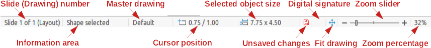
When a shape is drawn, select an object for editing, or add text to the drawing, the information field in the Status Bar (Figure 2) changes to reflect the action taken or in progress. See Chapter 1, Introducing Draw for more information on the Status Bar.
Figure 1: Drawing toolbar

Figure 2: Status Bar
Basic shapes, including text, are treated as objects in Draw. The default set of tools available for drawing basic shapes on the Drawing toolbar are shown in Figure 1. To add more tools to the Drawing toolbar, see Appendix B, Toolbars and the Getting Started Guide for more information.
Some tool icons on the Drawing toolbar change shape according to the last tool used from the selection of available tools. Each tool that has a downward pointing triangle ▼ to the right of the tool icon indicates that more tools are available. See “Drawing geometric shapes” below for information on the available shapes.
Note
When a basic shape is drawn, or one selected for editing, the information area at the left side in the status bar changes to reflect the present action. For example Line created, Text frame xxyy selected, and so on.
Figure 3: Line section on Properties deck in Sidebar
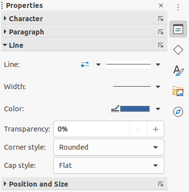
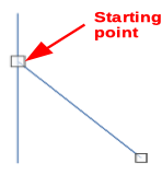
Figure 4: Line starting point
A straight line is the simplest element or object in Draw to create.
1) Use one of the following options to start drawing a straight line:
Click insert Line on the Drawing toolbar.
Click the triangle ▼ on the right of Lines and Arrows on the Drawing toolbar and select Insert Line from the drop-down list.
Click Insert Line in the Line section of the Shapes deck on the Sidebar (Figure 3).
2) Place the cursor at the starting point on the drawing, then click and drag the cursor to draw a straight line.
3) Release the mouse button when the end point is reached and a straight line is created. A selection handle appears at each end of the line, showing that this object is the currently selected object. The selection handle at the starting point of the line is slightly larger than the selection handle at the end point, as shown in Figure 4.
4) To snap the start and end points of a line to the grid, use one of the following methods:
Hold down the Ctrl key while drawing the line.
Go to View > Snap Guides on the Menu bar and select Snap to Grid from the available options.
To temporarily disable Snap to Grid when it has been selected, hold down the Ctrl key while drawing the line.
Note
To display the grid, go to View > Grid and Helplines on the Menu bar and select Display Grid. Alternatively, go to Tools > Options LibreOffice Draw > Grid and select Visible Grid.
5) To restrict the drawing angle of a line to a multiple of 45 degrees, use one of the following methods:
Keep the Shift key pressed while drawing the line.
However, if the option in the Constrain Objects section of
Go to Tools > Options > LibreOffice Draw > Grid and select When creating or moving objects in Constrain Objects.
To temporarily disable When creating or moving objects, hold down the Shift key while drawing the line.
6) To draw a line symmetrically outwards in both directions from the center of the line, hold down the Alt key while drawing the line.
Figure 5: Line dialog - Line page
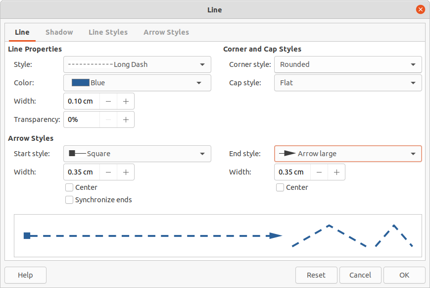
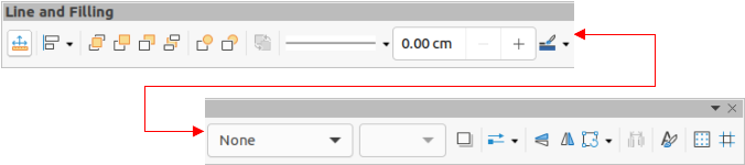
Figure 6: Line and Filling toolbar
When a line is drawn, it uses default attributes. To change any of these attributes and format a line to the drawing requirements, select a line by clicking on it and use one of the following methods to access formatting options for a line:
Go to the Properties deck on the Sidebar and open the Line section.
Right-click on a line and select Line from the context menu to open the Line dialog (Figure 5).
Go to Format > Line on the Menu bar to open the Line dialog.
Use the tools Line Style, Line Width, and Line Color on the Line and Filling toolbar (Figure 6).
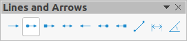
Draw classifies both lines and arrows as lines and are drawn like straight lines. Hovering the cursor over each tool in the Lines and Arrows sub-toolbar (Figure 7) indicates what type of line or arrow each tool will draw. The information field on the Status Bar shows them only as lines.
Note
The tool icon for the last tool used will already be selected on the Drawing toolbar. This makes it easier to use the same tool again.
Figure 7: Lines and Arrows sub-toolbar
1) Use one of the following methods to start drawing a line or arrow:
Click on the small triangle ▼ next to Lines and Arrows on the Drawing toolbar and select the type line or arrow required from the options available.
Select the type of line or arrow required in the Lines and Arrows section of the Shapes deck on the Sidebar (Figure 10).
2) Place the cursor at the starting point for the line or arrow, then click and drag the cursor. An arrowhead is drawn at the end point of an arrow when the mouse button is released.
3) For more information on options for drawing lines and arrows, see “Straight lines” above.
Figure 8: Line dialog - Arrow Styles page
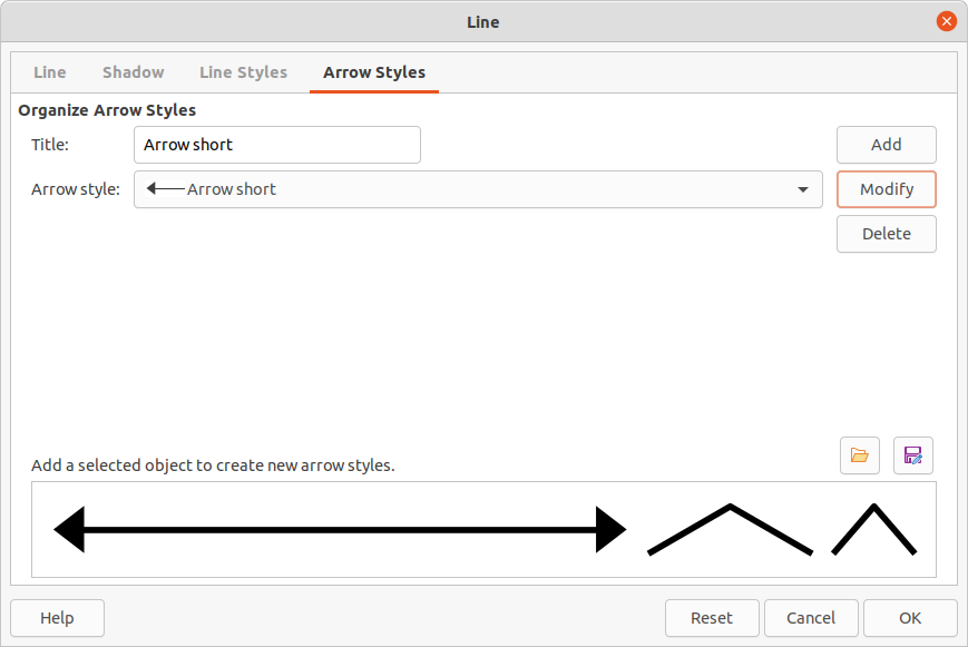
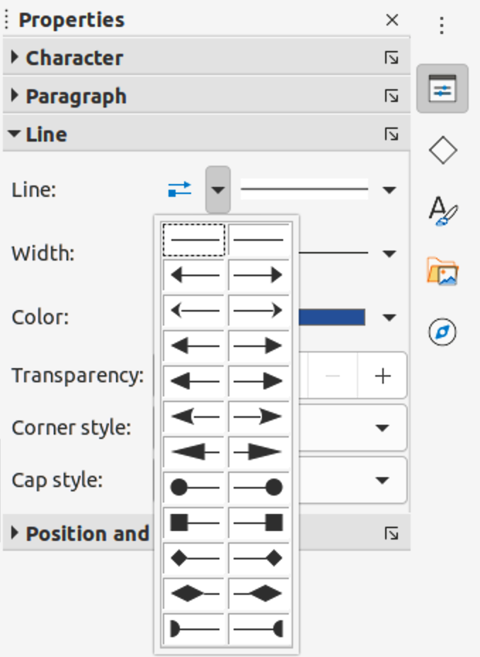
Figure 9: Arrow styles in Line section in the Properties deck on Sidebar
After drawing a line or arrow, make sure it is selected and format the line or arrow to the drawing requirements using one of the following methods:
To format a line, see “Straight lines” above for more information.
To format an arrow:
Go to Format > Line on the Menu bar or right-click on the arrow to open the Line dialog. Click on Arrow Styles to open the Arrow Styles page (Figure 8). Select an arrow style from the options available in the Arrow style drop-down list. Click OK to apply the arrow style. This changes both ends of the arrow to the same style.
Click on Arrow Style in the Line section on the Properties deck of the Sidebar to open a drop-down list (Figure 9) and select an arrow style. The arrow styles on the left change the start point arrow style. The arrow styles on the right change the end point arrow style.
Figure 10: Shapes deck on Sidebar
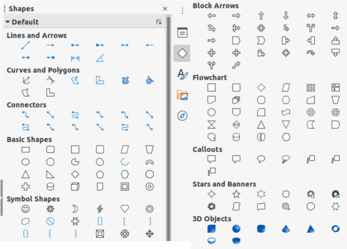
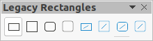
Figure 11: Legacy Rectangles toolbar
1) Use one of the following methods to start drawing a rectangle or square:
Click on Rectangle in the Drawing toolbar.
Select the type of rectangle or square in Basic Shapes on the Shapes deck in the Sidebar (Figure 10).
Click on the triangle ▼ to the right of Basic Shapes on the Drawing toolbar and select the type of rectangle or square required from the drop-down list.
Select the type of rectangle or square from the Legacy Rectangles toolbar (Figure 11). To display the Legacy Rectangles toolbar, go to View > Toolbars on the Menu bar and select it.
2) Place the cursor at the starting point for the rectangle or square, then click and drag the cursor until the required size is drawn.
3) If Rectangle is selected, hold down the Shift key to draw a square.
4) If Rectangle is selected, to draw a square from its center rather than the bottom right corner, hold down the Shift and Alt keys while dragging the cursor. The square uses the start point as the center of the square.
5) To draw a rectangle or square from its center rather than the bottom right corner, hold down the Alt key while dragging the cursor. The rectangle or square uses the start point as the center of the rectangle or square.
Note
If the option When creating or moving objects has been selected in the Constrain Object section of Tools > Options > LibreOffice Draw > Grid, the action of the Shift key reversed. A square is drawn instead of a rectangle. To draw a rectangle, hold down the Shift key. This reversal of the Shift key action also applies when drawing ellipses, circles, arcs, and segments.
1) Use one of the following methods to start drawing an ellipse or circle:
Click on Ellipse in the Drawing toolbar.
Select the type of ellipse or circle in Basic Shapes on the Shapes deck in the Sidebar.
Click on the triangle ▼ to the right of Basic Shapes on the Drawing toolbar and select the type of ellipse or circle required from the drop-down list.
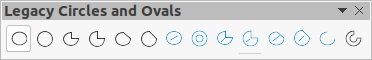
Select the type of ellipse or circle from the Legacy Circles and Ovals toolbar (Figure 12). To display the Legacy Circles and Ovals toolbar, go to View > Toolbars on the Menu bar and select it.
2) Place the cursor at the starting point for the ellipse or circle, then click and drag the cursor until the required size is drawn.
3) If Ellipse is selected, hold down the Shift key to draw a circle.
4) If Ellipse is selected, to draw a circle from its center rather than the bottom right corner, hold down the Shift and Alt keys while dragging the cursor. The circle uses the start point as the center of the circle.
5) To draw an ellipse or circle from its center rather than the bottom right corner, hold down the Alt key while dragging the cursor. The ellipse or circle uses the start point as the center of the ellipse or circle.
Figure 12: Legacy Circles and Ovals toolbar
Tip
To quickly insert a line, rectangle, ellipse, or text, press and hold down the Ctrl key and then click on one of the icons for Line, Rectangle, Ellipse, or Text and a standard sized object is drawn automatically in the work area. The size, shape, and color are all standard values. These attributes can be changed later, if desired. See Chapter 4 Changing Object Attributes for more information.
Dimension lines display a measurement of an object in the drawing (Figure 13). The dimension line does not belong to the object itself, but is positioned close to it. An object can have as many dimension lines as necessary to indicate the size of its sides, edges, and distances.
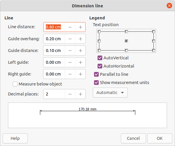
To control the display of a dimension line components and appearance by right-clicking, on the dimension line and selecting Dimensions from the context menu to open the Dimension line dialog (Figure 14).
1) Use one of the following options to start drawing a dimension line:
Click on the triangle ▼ on the right of Lines and Arrows on the Drawing toolbar and select Dimension Line from the drop-down list.
Click on Dimension Line in the Lines and Arrows section of the Shapes deck on the Sidebar.
2) Place the cursor at the point close to the object to position the start of the dimension line.
3) Click and drag to draw the dimension line. As the dimension line is drawn, the dimension is displayed and automatically calculated.
4) Format the settings of a dimension line using the options available the Dimension Line dialog. For more information dimension line options, see Chapter 11, Advanced Draw Techniques.
Figure 13: Measuring an object with dimension lines
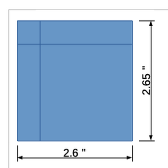
Figure 14: Dimension Line dialog
Note
The measurement units used for dimension lines can be changed by going to Tools > Options > LibreOffice Draw > Grid on the Menu bar and select a measurement unit from the available options in the Units of measurement drop-down list.
Tools for drawing arcs or segments (partial circles or ellipses) are available as follows:
Legacy Circles and Ovals toolbar.
Basic Shapes sub-toolbar.
Basic Shapes section in the Shapes deck on the Sidebar.
An arc or segment is drawn as follows:
1) Select the required tool from one of the options given above.
2) Click at the approximate start point and drag the cursor to start creating an arc or segment. Release the mouse button when the required object size is reached.
3) Move the cursor to the position where the arc or segment starts and click to start drawing the arc or segment. The Status Bar indicates the angle in degrees.
4) Move the cursor to the end position of where the arc or segment finishes. The Status Bar shows the angle in degrees.
5) Click again to complete the arc or segment.
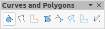
Figure 15: Curves and Polygons sub-toolbar
Tools for drawing curves, polygons, or freeform lines are available in the following places:
Click the triangle ▼ on the right of Curve and Polygons on the Drawing toolbar and select the type of curve, polygon or freeform line from the drop-down list.
Select the type of curve, polygon or freeform line in the Curve and Polygons section of the Shapes deck on the Sidebar.
Select the type of curve, polygon or freeform line from the Curves and Polygons sub‑toolbar (Figure Figure 15).
1) Click to create the starting point of the curve, then drag the cursor from the starting point to draw a line.
2) Release the mouse button and continue to drag the cursor to bend the line into the required curve shape.
3) Click to set the end point of the curve and position the curve on the drawing.
4) Continue dragging the cursor to draw straight lines at the end of the curve. Each mouse click sets a corner point and allows drawing of another straight line from each corner point.
5) Double-click to end the drawing of a curve and straight lines.
Note
A filled curve automatically joins the last point to the first point to close off the object and fills it with the selected fill. A curve without filling is not closed at the end of the drawing.
1) Click to create the start point, then drag the cursor to draw a line between the first and second points.
2) Move the cursor to draw the next line. Each mouse click sets a corner point and draws another line.
3) Double-click to end the drawing of a polygon.
Note
A filled polygon automatically joins the last point to the first point to close off the figure and fills it with the selected fill. A polygon without filling is not closed at the end of the drawing.
Like ordinary polygons, these are formed from lines, but the angles between lines are restricted to 45 or 90 degrees. If required, hold down the Shift key as the line is drawn so that the line is drawn at an angle other than 45 or 90 degrees.
Using the freeform line tools is similar to drawing with a pencil on paper.
1) Click and drag the cursor to the line shape required.
2) Release the mouse button to complete the drawing of the freeform line.
3) If Freeform Line Filled is selected, the end point is joined automatically to the start point and the object is filled with the selected fill.
Note
The points in curves, polygons and freeform lines can be moved and edited. See Chapter 3, Working with Objects and Chapter 11, Advanced Draw Techniques for more information.
All Draw objects have glue points, which are not normally displayed. Glue points become visible when Connectors is selected on the Drawing toolbar or a connector tool in the Connectors section on the Shapes deck in the Sidebar.
Most objects have four glue points (Figure 16). More glue points can be added and customized using the Glue Points toolbar (Figure 17). Go to View > Toolbars > Glue Points on the Menu bar to open the toolbar.
Glue points are not the same as the selection handles of an object. Selection handles are for moving or changing the shape of an object. Glue points are used to fix or glue a connector to an object so that when the object moves, the connector stays fixed to the object. For a more detailed description on the use of glue points, see Chapter 3, Working with Objects and Object Points and Chapter 8, Connections, Flowcharts, and Organization Charts.
Figure 16: Glue points example
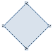
Figure 17: Glue Points toolbar
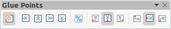
Figure 18: Connector between two objects
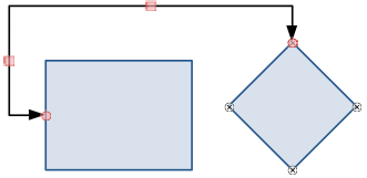
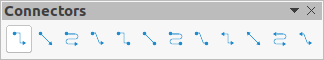
Figure 19: Connectors sub-toolbar
Connectors are lines or arrows whose ends automatically snap to a glue point of an object. Connectors are not the same as lines and arrows. When objects are moved or reordered, the connectors remain attached to a glue point. Figure 18 shows an example of two objects and a connector.
Draw offers a range of different connectors and connector functions. On the Drawing toolbar, click on the triangle ▼ next to Connectors to open the Connectors sub-toolbar (Figure 19), or select a connector from the Connectors section in the Shapes deck in the Sidebar. For a more detailed description of the use of connectors, see Chapter 8, Connections, Flowcharts, and Organization Charts.
The tools for drawing geometric shapes are located on the Drawing toolbar and on the Shapes deck in the Sidebar. The use of these tools for geometric shapes is similar to the tools used for drawing rectangles and squares, or ellipses and circles. For more information, see “Drawing basic shapes” above.
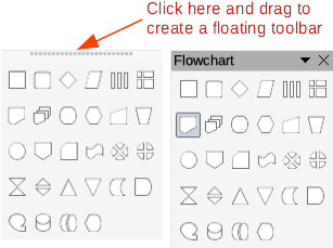
Figure 20: Creating floating toolbar
The tool icons on the Drawing toolbar, used for drawing geometric shapes, always indicate the last geometric shape drawn and may not be the same as the tool icons shown on the Drawing toolbar in this chapter. This also makes it easier to use the same tool again.
Clicking on the triangle ▼ to the right of a tool icon on the Drawing toolbar opens a sub-toolbar giving access to the toolset for that shape. If necessary, this sub-toolbar can be “torn off” to create a floating toolbar.
Click the dotted line at the top of the toolset as shown in Figure 20, drag it across the screen to the Workspace and release the mouse button to create a floating toolbar
To close a floating toolbar, click on the X on the right of the toolbar title.
Note
Text can be added to all of these geometric shapes. For more information, see Chapter 11, Advanced Draw Techniques.
Click on the triangle ▼ to the right of Basic Shapes on the Drawing toolbar opens the Basic Shapes sub-toolbar (Figure 21). This sub-toolbar also includes rectangle and ellipse tools that are identical to the ones already displayed on the Drawing toolbar. Alternatively, select the required tool in the Basic Shapes section in the Shapes deck on the Sidebar.
Figure 21: Basic Shapes sub-toolbar

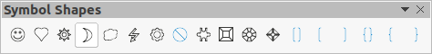
Click on the triangle ▼ to the right of Symbol Shapes on the Drawing toolbar opens the Symbol Shapes sub-toolbar (Figure 22). Alternatively, select the required tool in the Symbol Shapes section in the Shapes deck on the Sidebar.
Figure 22: Symbol Shapes sub-toolbar
Click on the triangle ▼ to the right of Block Arrows on the Drawing toolbar opens the Block Arrows sub-toolbar (Figure 23). Alternatively, select the required tool in the Block Arrows section in the Shapes deck on the Sidebar.
Figure 23: Block Arrows sub-toolbar

Click on the triangle ▼ to the right of Flowchart on the Drawing toolbar opens the Flowchart sub‑toolbar (Figure 24) for symbols. Alternatively, select the required tool in the Flowchart section in the Shapes deck on the Sidebar. The creation of flowcharts, organization charts, and similar planning tools are further described in Chapter 8 Connections, Flowcharts and Organization Charts.
Figure 24: Flowchart sub-toolbar

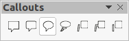
Click on the triangle ▼ to the right of Callout to on the Drawing toolbar opens the Callouts sub‑toolbar (Figure 25). Alternatively, select the required tool in the Callouts section on the Shapes deck on the Sidebar.
Figure 25: Callouts sub‑toolbar
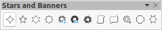
Click on the triangle ▼ to the right of Star and Banners on the Drawing toolbar opens the Stars and Banners sub-toolbar (Figure 26). Alternatively, select the required tool in the Stars and Banners section in the Shapes deck on the Sidebar.
Figure 26: Stars and Banners sub-toolbar
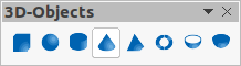
Click on the triangle ▼ to the right of 3D Objects on the Drawing toolbar opens the 3D-Objects sub‑toolbar (Figure 27). Alternatively, select the required tool in the 3D-Objects section in the Shapes deck on the Sidebar.
Figure 27: 3D-Objects sub-toolbar
In Draw text can be added, inserted, and formatted to a drawing, objects, and shapes. For more information on how to add, insert, and format text in a drawing or drawing objects, see Chapter 9, Adding and Formatting Text.