Draw Guide 7.1
Chapter 5,
Combining Multiple Objects
This document is Copyright © 2021 by the LibreOffice Documentation Team. Contributors are listed below. This document maybe distributed and/or modified under the terms of either the GNU General Public License (https://www.gnu.org/licenses/gpl.html), version 3 or later, or the Creative Commons Attribution License (https://creativecommons.org/licenses/by/4.0/), version 4.0 or later.
All trademarks within this guide belong to their legitimate owners.
|
Peter Schofield |
Winston Min Tjong |
Jean Hollis Weber |
|
John Cleland |
Martin Fox |
Jean Hollis Weber |
|
John A Smith |
Peter Schofield |
Hazel Russman |
|
Claire Wood |
|
|
Please direct any comments or suggestions about this document to the Documentation Team’s mailing list: documentation@global.libreoffice.org
Note
Everything sent to a mailing list, including email addresses and any other personal information that is written in the message, is publicly archived and cannot be deleted.
Published July 2021. Based on LibreOffice 7.1 Community. Other versions of LibreOffice may differ in appearance and functionality.
Some keystrokes and menu items are different on macOS from those used in Windows and Linux. The table below gives some common substitutions for the instructions in this document. For a detailed list, see the application Help.
|
Windows or Linux |
macOS equivalent |
Effect |
|
Tools > Options |
LibreOffice > Preferences |
Access setup options |
|
Right-click |
Control +click and/or right-click depending on computer setup |
Open a context menu |
|
Ctrl (Control) |
⌘ (Command) |
Used with other keys |
|
F11 |
⌘+T |
Open the Styles deck in the Sidebar |
Grouping of objects is similar to putting objects into a container. Objects can be moved as a group and global changes applied to the objects within the group. A group can always be undone and the objects that make up the group can always be manipulated separately.
A temporary grouping is when several objects are selected. Any changes to object parameters are applied to all of the objects within the temporary group. For example, a temporary group of objects can be rotated in its entirety.
A temporary group is created using one of the following methods:
Click and drag the cursor over several objects surrounding the objects with a selection rectangle (this selection rectangle is also known as a marquee). Release the mouse button when all the objects required for a temporary group are selected.
Click the first object, then hold down the Shift key and click on the remaining objects for the temporary group.
To cancel a temporary group of objects, simply click outside of the selection handles displayed around the objects.
When objects are grouped, any editing operations carried out on the group are applied to all objects within the group. Click on one object in a group, and the whole group is selected.
The objects within a group retain their own individual properties and can be edited independently. See “Editing individual group objects” below for more information.
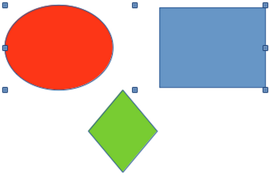
1) Select the objects for a group using one of the following methods. Selection handles appear around all the objects selected for the group (Figure 1).
Click on each object in turn while holding down the Shift key.
Make sure Select on the Drawing toolbar is selected and draw a selection rectangle around the objects required for the group using the cursor.
2) Create the group of selected objects using one of the following methods:
Right-click on the group and select Group from the context menu.
Go to Shape > Group > Group on the Menu bar.
Use the keyboard shortcut Ctrl+Shift+G.
Figure 1: Grouping objects
1) Select the group of objects and selection handles appear around the objects within the group (Figure 1).
2) Ungroup the group of objects using one of the following methods:
Right-click on the group and select Ungroup from the context menu.
Go to Shape > Group > Ungroup on the Menu bar.
Use the keyboard shortcut Ctrl+Alt+Shift+G.
An object within a group can be edited individually without ungrouping the objects.
1) Select a group, then enter the group using one of the following methods. After entering a group, objects outside the group cannot be selected for editing.
Right-click on the group and select Enter Group from the context menu.
Go to Shape > Group > Enter Group on the Menu bar.
Use the keyboard shortcut F3.
Double-click on the selected group.
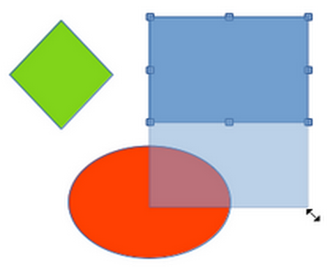
2) Once inside the group, click on any object to select and individually edit it (Figure 2).
3) After making changes to an individual object, exit the group using one of the following methods:
Right-click on the group and select Exit Group from the context menu.
Go to Shape > Group > Exit Group on the Menu bar
Use the keyboard combination Ctrl+F3.
Double-click outside the group.
Figure 2: Editing objects within a group
A group of groups can be created and this is commonly known as nesting groups. When nested groups are created, Draw retains the individual group hierarchy and remembers the order in which groups were selected. That is, the last individual group selected will be on top of all the other groups within a nested group. Ungrouping and entering a nested group works in exactly the same way as for individual groups.
Combining objects is a permanent merging of objects creating a new object. The original objects are no longer available as individual objects and cannot be edited as individual objects. Any editing of a combined object affects all the objects that were used when combination was carried out.
1) Select several objects for combining.
2) Combine the selected objects into a single object using one of the following methods:
Right-click on the selection and select Shapes > Combine from the context menu.
Go to Shape > Combine on the Menu bar.
Use the keyboard combination Ctrl+Shift+K.
At first glance, the results can seem rather surprising, but the following points explain how combining objects works.
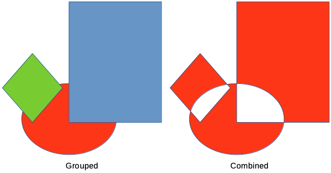
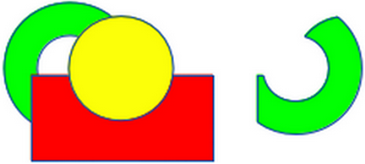
The attributes (for example, area fill) of the resulting object are those of the object furthest back. In Figure 3, it is the ellipse and Figure 4 it is the yellow rectangle.
Where the objects overlap, the overlapping zone is either filled or empty depending on whether the overlap is even numbered or odd numbered. Figure 4 shows that where the overlap number is even, an empty space is created and where the overlap number is odd, a filled area is created.
Figure 3: Combining objects
Tip
Objects can be reordered so they are further back or further forward in the arrangement order. Right-click on the object and select Arrangement from the context menu and select one of the options available. For more information, see “Arranging objects” below.
Figure 4: Example of area fill when combining overlapping objects
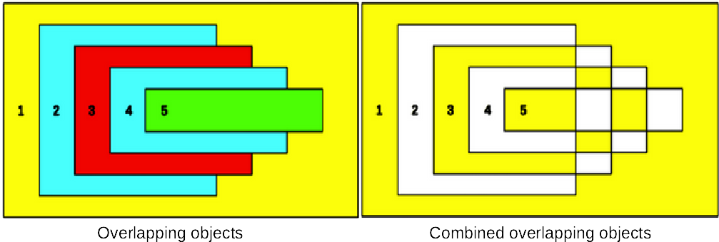
Figure 5: Example of splitting a combined object
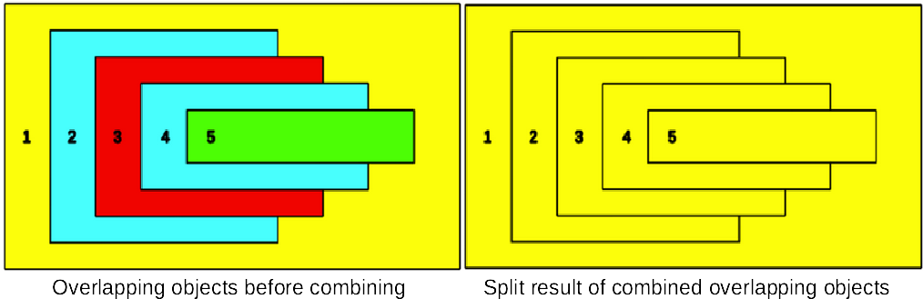
An object which has been combined from several objects can be split into individual objects. However, the original objects retain the formatting of the combined object and do not revert back to their original formatting.
Select the combined object and use one of the following methods to split the combined object:
Go to Shape > Split on the Menu bar.
Use the keyboard shortcut Ctrl+Alt+Shift+K.
In Figure 5, the left graphic is the original example of overlapping area fills before combining. The right graphic is the result of splitting the combined object. The individual overlapping objects have taken the formatting of the object at the back of the overlapping objects.
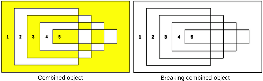
When an object is combined from several objects, the combined object can be broken into its constituent parts by going to Shape > Break on the Menu bar. This means that the original objects are broken into their constituent parts; for example, a rectangle is broken into four separate lines and the area is lost, as shown by the right graphic in Figure 6.
Figure 6: Example of breaking a combined object
The constituent parts of an object can be connected together by selecting all the constituent parts of the object and going to Shape > Connect on the Menu bar. This connects the parts together and closes the object, resulting in the area becoming filled with the area fill it had before the object was broken.
After selecting more than one object, the merge, subtract, and intersect functions become available. This allows creation of a new object with a new shape.
When merging objects, a new object is created with a shape that follows the shape of the merged objects. The area fill of the merged object is determined by the area fill of the object that is at the rear of all the other objects, as shown in Figure 7.
After selecting several objects, use one of the following methods to merge the objects:
Go to Shape > Merge on the Menu bar.
Right-click on the selected objects and select Shapes > Merge from the context menu.
Figure 7: Merging objects

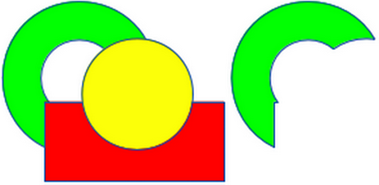
When subtracting objects, the objects at the front are subtracted from the object behind. This leaves a blank space that the subtracted objects occupied creating a new shape, as shown in Figure 8. After selecting several objects that overlap each other, use one of the following methods to subtract objects:
Go to Shape > Subtract on the Menu bar.
Right-click on the selected objects and select Shapes > Subtract from the context menu.
Figure 8: Subtracting objects
When intersecting objects, the front objects and the exposed area of the object at the rear are removed. This creates a new object from the area of the object at the rear that was covered by the objects at the front, as shown in Figure 9.
After selecting several objects that overlap each other, use one of the following methods to intersect objects:
Go to Shape > Intersect on the Menu bar.
Right-click on the selected objects and select Shapes > Intersect from the context menu.
Figure 9: Intersecting objects
The following example shows how to use the merge, subtract, and intersect functions to create a knife with a wooden handle.
|
Draw an ellipse and then a rectangle overlapping half of its width. |
|
|
Select both shapes, right-click, and select Shapes > Subtract from the context menu. |
|
|
Draw another rectangle and put it over the top half of the ellipse. |
|
|
Select both shapes, right-click, and select Shapes > Subtract from the context menu. |
|
|
Draw a small ellipse covering just the lower right corner. |
|
|
Select both shapes, right-click, and select Shapes > Subtract from the context menu. The knife blade shape is now complete. |
|
|
To make the handle, draw a rectangle and an ellipse. |
|
|
Merge the shapes together. |
|
|
Position the handle on the blade. Select the handle and blade, then group together to create a drawing of the knife. |
|
Duplication makes copies of an object while applying a set of changes (such as color or rotation) to the duplicates.
1) Select an object or group of objects, then use one of the following methods to open the Duplicate dialog (Figure 10):
Go to Edit > Duplicate on the Menu bar.
Go to Shape > Duplicate on the Menu bar.
Use the keyboard shortcut Shift+F3.
2) Select the number of copies, placement, enlargement, and the start and end colors for duplicate copies.
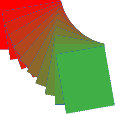
3) Click OK and duplicate copies are created. An example of a duplication is shown in Figure 11. Each duplicate object is a separate object.
4) To group the duplicate objects into one group, see “Grouping objects” above.
5) To combine the duplicate objects into one object, see “Combining objects” above.
The following options are available when using the Duplicate dialog:
Number of copies – enter the number of copies required.
Placement – sets the position and rotation of duplicated objects in relation to the original object.
X axis-- enter the horizontal distance between the centers of the selected object and the duplicate objects. Positive values shift the duplicate object to the right and negative values shift the duplicate object to the left.
Y axis – enter the vertical distance between the centers of the selected object and the duplicate objects. Positive values shift the duplicate object down and negative values shift the duplicate object up.
Angle – enter the angle (0 to 359 degrees) required for rotating the duplicate object. Positive values rotate the duplicate objects in a clockwise direction and negative values in a counterclockwise direction.
Figure 10: Duplicate dialog
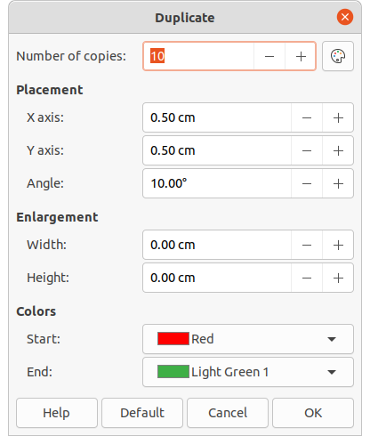
Figure 11: Duplication example
Enlargement – sets the size of the duplicate objects.
Width – enter the amount to enlarge or reduce the width of the duplicate objects.
Height – enter the amount to enlarge or reduce the height of the duplicate objects.
Colors – sets the colors for the selected object and the duplicate objects. For more than one copy, these colors define the start and end points of a color gradient.
Start – select a color for the selected object.
End – select a color for the duplicate object. If making more than one copy, this color is applied to the last copy.
Cross-fading transforms one object shape into another object shape. The result is a new group of individual objects that includes the start and end objects. The intermediate steps show the transformation from one object shape to another object shape. The cross-fading is carried out from the first object selected to the second object selected.
1) Select two objects and go to Shape > Cross-fading on the Menu bar to open the Cross‑fading dialog (Figure 12).
2) Select the number of Increments for the transformation.
3) If necessary, select Cross-fade attributes and Same orientation.
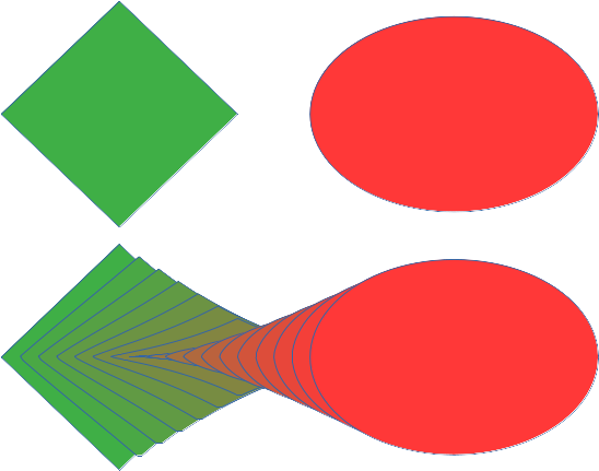
4) Click OK to cross-fade the selected objects and close the Cross-fading dialog. An example of cross-fading is shown in Figure 13 with Same orientation deselected. The object created is a group of objects.
5) To ungroup this group of objects and use the individual objects, see “Ungrouping” above.
Figure 12: Cross-fading dialog
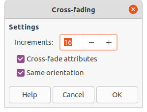
Figure 13: Cross-fading example
The following options are available in the Cross-fading dialog:
Increments – enter the number of steps to be created between the selected objects.
Cross-fade attributes – applies cross-fading to the line and fill properties of the selected objects. For example, if the selected objects are filled with different colors, a color transition between the two colors is applied.
Same orientation – applies a smooth transition between the selected objects.
When combining, merging, subtracting, or intersecting objects, the end result varies depending on which object is at the front and which object is at the back. Each new object placed on a drawing automatically becomes the front object and all the other objects move backwards in positioning order. Arranging objects changes the order in of a group of objects.
To change the arrangement position of an object, select one or more objects and then use one of the following methods
Right-click on the selected object(s), then select Arrange from the context menu and one of the available options.
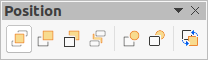
Click on small triangle ▼ to the right of Arrange on the Standard toolbar to open the Position toolbar (Figure 14).
Click one of the arrangement tools on the Line and Filling toolbar.
Click on Shape > Arrange on the Menu bar and select an arrangement option.
Use the Arrange tools in Position and Size section in the Properties deck on the Sidebar.
Use a keyboard shortcut given below.
Figure 14: Position toolbar
The arrangement options available are as follows:
Bring to Front (Shift+Ctrl++) – brings the selected object to the front of a group of objects.
Bring Forward (Ctrl++) – brings the selected object forward one step.
Send Backward (Ctrl+–) – sends the selected object one step backward.
Send to Back (Shift+Ctrl+–) – sends the selected object to the back of a group of objects.
In Front of Object – moves the selected object in front of another selected object.
Behind Object – moves the selected object behind another selected object.
Reverse – reverses the order of the selected objects. This tool is grayed out if only one object is selected.
Note
The positioning tools can be turned into a floating toolbar by clicking at the top of the pop-up on the Standard toolbar and dragging it to a new position on a drawing, as shown in Figure 14.
To make a drawing look more professional, objects can be aligned with each other. Select one or more objects and use one of the following methods to align objects:
Right-click on the selected object(s), then select Align Objects from the context menu and one of the available options.
Click on small triangle ▼ to the right of Align on the Standard or Line and Filling toolbars to open a pop-up toolbar.
Go to Shape > Align on the Menu bar and select the alignment required.
Use the Align tools in the Position and Size section in the Properties deck on the Sidebar.
The alignment tools available are as follows:
Left – aligns the left edges of the selected objects. If only one object is selected, the left edge of the object is aligned to the left page margin.
Centered – horizontally centers the selected objects. If only one object is selected, the center of the object is aligned to the horizontal center of the page.
Right – aligns the right edges of the selected objects. If only one object is selected, the right edge of the object is aligned to the right page margin.
Top – vertically aligns the top edges of the selected objects. If only one object is selected, the top edge of the object is aligned to the upper page margin.
Center – vertically centers the selected objects. If only one object is selected, the center of the object is aligned to the vertical center of the page.
Bottom – vertically aligns the bottom edges of the selected objects. If only one object is selected, the bottom edge of the object is aligned to the lower page margin.
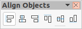
Figure 15: Align Objects toolbar
Note
The alignment tools can be turned into a floating toolbar by clicking at the top of the pop-up toolbar and dragging it to a new position on a drawing workspace, as shown in Figure 15.
Distributing objects allows three or more objects to be evenly spaced along a horizontal axis or vertical axis. Objects are distributed using the outermost objects in the selection as base points for spacing.
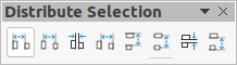
Figure 16: Distribute Selection toolbar
Select at least three objects, then use one of the following methods to distribute the objects:
Right-click on the selected objects, then select Distribute Selection from the context menu and one of the available options.
Click on small triangle ▼ to the right of Distribute Selection on the Standard toolbar to open a pop-up toolbar.
Go to Shape > Distribute Selection on the Menu bar and select a distribution option.
Right-click on the selected objects and select Distribute Selection from the context menu, then select a distribution option.
The distribution options available are as follow:
Horizontal Left – distributes the selected objects so that the left edges of the objects are evenly spaced from one another.
Horizontal Center – distributes the selected objects so that the horizontal centers of the objects are evenly spaced from one another.
Horizontal Spacing – distributes the selected objects horizontally so that the objects are evenly spaced from one another.
Horizontal Right – distributes the selected objects so that the right edges of the objects are evenly spaced from one another.
Vertical Top – distributes the selected objects so that the top edges of the objects are evenly spaced from one another.
Vertical Center – distributes the selected objects so that the vertical centers of the objects are evenly spaced from one another.
Vertical Spacing – distributes the selected objects vertically so that the objects are evenly spaced from one another.
Vertical Bottom – distributes the selected objects so that the bottom edges of the objects are evenly spaced from one another.
Note
The distribution tools can be turned into a floating toolbar by clicking at the top of the pop-up toolbar and dragging it to a new position on a drawing workspace, as shown in Figure 16.