Draw Guide 7.1
Chapter 8,
Connections, Flowcharts, and Organization Charts
This document is Copyright © 2021 by the LibreOffice Documentation Team. Contributors are listed below. This document maybe distributed and/or modified under the terms of either the GNU General Public License (https://www.gnu.org/licenses/gpl.html), version 3 or later, or the Creative Commons Attribution License (https://creativecommons.org/licenses/by/4.0/), version 4.0 or later.
All trademarks within this guide belong to their legitimate owners.
|
Peter Schofield |
Jean Hollis Weber |
|
|
John Cleland |
Martin Fox |
Jean Hollis Weber |
|
John A Smith |
Peter Schofield |
Regina Henschel |
|
Claire Wood |
|
|
Please direct any comments or suggestions about this document to the Documentation Team’s mailing list: documentation@global.libreoffice.org
Note
Everything sent to a mailing list, including email addresses and any other personal information that is written in the message, is publicly archived and cannot be deleted.
Published July 2021. Based on LibreOffice 7.1 Community. Other versions of LibreOffice may differ in appearance and functionality.
Some keystrokes and menu items are different on macOS from those used in Windows and Linux. The table below gives some common substitutions for the instructions in this document. For a detailed list, see the application Help.
|
Windows or Linux |
macOS equivalent |
Effect |
|
Tools > Options |
LibreOffice > Preferences |
Access setup options |
|
Right-click |
Control+click or right-click depending on computer setup |
Open a context menu |
|
Ctrl (Control) |
⌘ (Command) |
Used with other keys |
|
F11 |
⌘+T |
Open the Styles deck in the Sidebar |
Connectors and glue points were briefly introduced in Chapter 2 Drawing Basic Shapes. This section describes them in more detail and how to use them.
Connectors are lines or arrows whose ends automatically dock to a connection or glue point on the border of an object. Connectors are useful in drawings because connecting lines between objects remain connected to objects, even when objects are moved or rearranged. Also, when an object with a connector attached is moved or resized, the connector automatically adjusts its shape to accommodate the changes.
For example, when creating flowcharts, organization chart, schematics, or diagrams, it is highly recommended to use connectors instead of simple lines. Using connectors removes the need to redraw lines between objects,
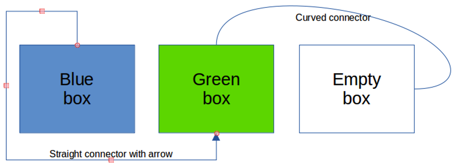
When a connector is drawn or selected, Draw displays selection handles that are different to the selection handles for normal lines or objects. The termination points of a connector are round at the start and end points of a connector, and square in the center of the lines that make up a connector, as shown by the example in Figure 1. The square selection handles on a connector are used to change the routing of a connector where applicable.
Figure 1: Example of connectors between objects
Draw has a comprehensive selection of connectors to connect objects together, for example, in a flowchart or organization chart. The default set of connectors can be accessed using one of the following methods:
Click the triangle ▼ to the right of Connectors on the Drawing toolbar. The Connectors icon changes shape depending on the last connector used.
Select a connector from the options available in the Connectors section in the Shapes deck on the Sidebar.
If necessary, the connectors on the Drawing toolbar can be displayed as a Connectors floating toolbar as follows:
1) Click on the triangle ▼ on the right of Connectors on the Drawing toolbar.
2) Click at the top of the pop up toolbar and drag it on to the Workspace.
3) Release the mouse button and the pop up toolbar becomes the Connectors floating toolbar (Figure 2).
Figure 2: Connectors floating toolbar
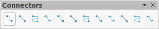
Figure 3: Available connects for Connectors toolbar
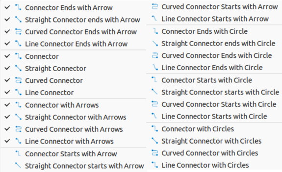
The full range of predefined connectors can be accessed by clicking on the triangle ▼ on the right of the titlebar for the Connectors toolbar and selecting Visible Buttons (Figure 3) from the context menu. Depending on the computer system being used, the connectors already installed on the toolbar are indicated either by a check mark against the name, or the connector icon is highlighted.
The connectors available fall into four type groups, as follows:
Standard – connector name starts with Connector. Line segments run vertically and horizontally. Creates a connector with one or more 90 degree angle bends. Click on an object glue point, then drag the cursor to a glue point on another object to create a standard connector.
Line – connector name starts with Line. Consists of a line segment with two smaller segments at the ends and draws a connector that bends near a glue point. Click on an object glue point, then drag to a glue point on another object to create a line connector. To adjust the length of the line segment between a bend point and a glue point, click on the connector and drag the bend point.
Straight – connector name starts with Straight. Consists of a single line and draws a straight line connector. Click on an object glue point, then drag the cursor to a glue point on another object to create a straight connector.
Curved – connector name starts with Curved. Based on Bézier curves, a curved connector bends around objects. Draws a curved line connector. Click on an object glue point, then drag the cursor to a glue point on another object to create a curved connector.
1) Click on the triangle ▼ on the right of Connectors on the Drawing toolbar to open the options available for selecting connectors (Figure 2 and Figure 3).
2) Select the type of connector required. See “Connector types” above for more information on connector types.
Figure 4: Example of object glue points
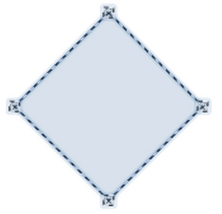
3) Move the cursor over one of the objects to be connected and small crosses appear around the object edges, normally in the same position as object selection handles. These crosses are the glue points to which a connector can be attached (Figure 4). See “Glue points” below for more information on glue points.
4) Click on the required glue point to attach the start point of the connector, then click and drag the cursor to draw a connector to another object.
5) When the cursor is over a glue point of the target object release the mouse button and the connector is drawn. The connector end point is attached to the glue point.
6) The square selection handles that appear on the connector are used to adjust the path of the connector so that it does not cover any other object in its path. See “Modifying connectors” below on how to change the connector route to avoid any objects the connector crosses over.
Note
The end point of a connector can be positioned in an empty part of a document. When the mouse button is released, the unattached end point of the connector is locked into place until it is moved to a different location.
Note
The start and end points of a connector cannot be swapped, that is the start point becomes the end point and the end point becomes the start point. To swap the end points of a connector, a new connector has to be drawn in the opposite direction.
To detach or reposition a connector, click and drag either round end point of a connector line to a different location. See the example in Figure Figure 1 for an example of round end points.
To change the connector route between objects so that the connector does not overlap any objects on the route, click on a square control point on the connector line and drag it to a new position. See the example in Figure Figure 1 for an example of square control points.
To modify a connector, right-click on the connector and select Connector from the context menu to open the Connector dialog (Figure 5). Use this dialog to change connector type and its properties.
Type – select the connector type from the drop-down list. See “Connector types” above for more information.
Figure 5: Connector dialog
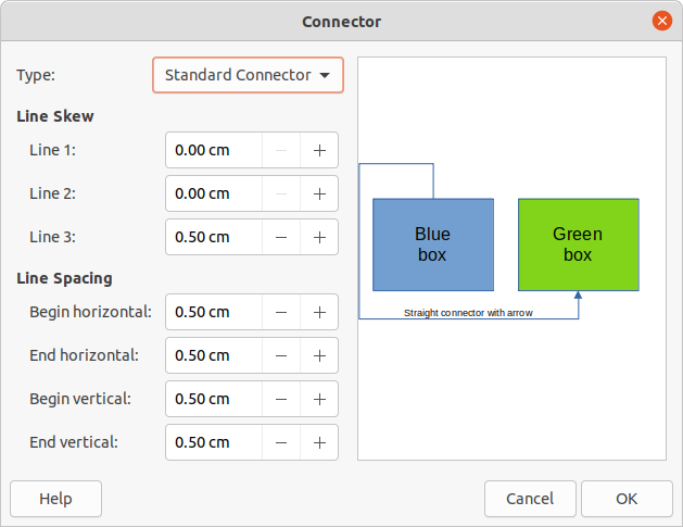
Line skew – defines the skew of a connector line. The dialog preview displays the result of any changes.
Line spacing – sets the spacing around a connector.
Begin horizontal – enter the amount of horizontal space required at the beginning of a connector.
Begin vertical – enter the amount of vertical space required at the beginning of a connector.
End horizontal – enter the amount of horizontal space required at the end of a connector.
End vertical – enter the amount of vertical space required at the end of a connector
Preview box – displays a preview of objects and connectors being used. A left click zooms in on the preview and a right-click zooms out.
Glue points are not the same as object selection handles. The selection handles are for moving or changing the shape of an object (see Chapter 3, Working with Objects for more information). Glue points are used to fix or glue a connector to an object so that when the object moves, the connector stays fixed to that object.
All objects have glue points, which are not normally displayed and only become visible when one of the following methods is used, Figure 4 shows an example of glue points visible on an object after a connector has been selected.
Connectors is selected on the Drawing toolbar. The Connectors icon displayed on the Drawing toolbar is the connector type that had been previously used.
A connector type is selected in the Connectors section in the Shapes deck on the Sidebar.
Figure 6: Glue Points toolbar
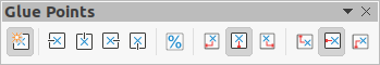
To add, customize or delete glue points to an object, go to View > Toolbars > Glue Points on the Menu bar to activate the Glue Points toolbar (Figure 6). This toolbar only becomes visible after using one of the following methods:
Click on Show Glue Point Functions on the Standard or Drawing toolbars.
Select Edit > Glue Points on the Menu bar.
Note
Show Glue Point Functions on the Drawing toolbar is not part of the default set of tools for the Drawing toolbar. To add this tool, right-click in an empty area on the Drawing toolbar and select Visible Buttons > Glue Points from the context menu.
When the Glue Points toolbar opens, only the five tools on the left of Glue Point Relative are active. The remaining six tools on the right of the toolbar only become active when Glue Point Relative is deselected.
Insert Glue Point – inserts a glue point at the cursor position in an object when the mouse button is clicked.
Exit Direction Left – connector attaches to the left edge of the selected glue point.
Exit Direction Top – connector attaches to the top edge of the selected glue point.
Exit Direction Right – connector attaches to the right edge of the selected glue point.
Exit Direction Bottom – connector attaches to the bottom edge of the selected glue point.
Glue Point Relative – when selected, the glue point moves when the object is resized maintaining its position relative to the object borders. When deselected, a glue point can be repositioned after the object is resized. This tool is selected by default when the Glue Point toolbar opens. The following six tools only become active when Glue Point Relative is deselected.
Glue Point Horizontal Left – when the object is resized, the selected glue point remains fixed at the left edge of the object.
Glue Point Horizontal Center – when the object is resized, the selected glue point remains fixed at the center of the object.
Glue Point Horizontal Right – when the object is resized, the selected glue point remains fixed at the right edge of the object.
Glue Point Vertical Top – when the object is resized, the selected glue point remains fixed at the top edge of the object.
Glue Point Vertical Center – when the object is resized, the selected glue point remains fixed at the vertical center of the object.
Glue Point Vertical Bottom – when the object is resized, the selected glue point remains fixed at the bottom edge of the object.
Note
Each glue point added to an object can have only one horizontal position and one vertical position. Only one of the horizontal position tools and one of the vertical position tools can be selected and used at any one time.
By default, most objects normally have four glue points as shown in the example in Figure 4. Add additional glue points to an object as follows:
1) Go to View > Toolbars > Glue Points on the Menu bar to activate the Glue Points toolbar.
2) Make sure no objects are selected and use one of the following methods to open the Glue Points toolbar:
Click on Show Glue Point Functions on the Standard or Drawing toolbars.
Select Edit > Glue Points on the Menu bar.
3) Select the object, then click on Insert Glue Point on the Glue Points toolbar.
4) Move the cursor to the required position on the selected object and the cursor changes shape to a cross (depending on the computer setup).
5) Click once to add a glue point. To add more glue points, move the cursor to a new position and click.
6) When finished adding glue points, move the cursor off the selected object and click in an empty space to deselect the object.
7) Alternatively, right-click on a glue point previously added to the object and select Insert Glue Point from the context menu, then click and drag the new glue point to the required position.
8) Select the type of glue point required from the options available on the Glue Points toolbar. See “Glue point types” above for more information.
Note
When an object has no fill, a glue point can only be added to the border of an empty object.
Tip
When adding, moving or customizing glue points, it is recommended to use the zoom function to make it easier to work with glue points. See Chapter 3, Working with Objects for more information. Also, glue points snap to the grid making it easier to position a glue point.
Only glue points that have been added to an object can be customized. The default glue points included with an object cannot be customized.
Customize the exit direction for a glue point that has been added to an object as follows:
1) Go to View > Toolbars > Glue Points on the Menu bar to activate the Glue Points toolbar.
2) Open the Glue Points toolbar:
3) Double-click on a glue point that has been added to an object to select the glue point for customization.
4) Select the exit direction required for the connector to be attached to the glue point using one of the following methods:
Click on the exit direction in the Glue Points toolbar.
Right-click on the glue point and select the exit direction from the context menu.
Customize the horizontal and vertical positioning for a glue point that has been added to an object as follow:
1) Go to View > Toolbars > Glue Points on the Menu bar to activate the Glue Points toolbar.
2) Open the Glue Points toolbar:
3) Double-click on a glue point that has been added to an object to select the glue point for customization.
4) Click on Glue Point Relative on the Glue Points toolbar to deselect this tool, or right-click on the glue point and select Glue Point Relative from the context menu to deselect the tool.
5) Select the horizontal and vertical positioning tools required for the glue point using one of the following methods Only one horizontal positioning tool and one vertical positioning tool can be used at any one time:
Click on the horizontal and vertical positioning required in the Glue Points toolbar.
Right-click on the glue point and select the horizontal and vertical positioning required from the context menu.
Only glue points that have been added to an object can be deleted. The default glue points included with an object cannot be deleted.
1) Select a glue point for deletion that has previously been added to the object.
2) Press the Delete key or go to Edit > Cut on the Menu bar.
Text can be easily added to connectors, then formatted, for example, to make a flowchart or organization chart easier to follow. See Chapter 9, Adding and Formatting Text for more information on working with and formatting text.
1) Select a connector and the control points become active.
2) Click on Insert Text Box or Insert Vertical Text (if added) on the Standard toolbar (Figure 7) or Drawing toolbar (Figure 8) to enter text mode. A flashing text cursor appears close to the connector and the Text Formatting toolbar (Figure 9) opens.
Alternatively, use the keyboard shortcut F2 to create horizontal text on the selected connector.
3) Type the required text for the connector.
4) If necessary, format the connector text. See “Formatting and editing text” below for more information on formatting and editing text text.
Figure 7: Standard toolbar with Insert Vertical Text added

Figure 8: Drawing toolbar with Insert Vertical Text added
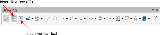
Figure 9: Text Formatting toolbar

5) When adding and formatting text is complete, move the cursor away from the text and connector, then click to end text mode. This also closes the Text Formatting toolbar.
Note
In the default installation of LibreOffice, the Insert Vertical Text tool is not included on the Standard or Drawing toolbars. To add Insert Vertical Text to the toolbar, right-click in an empty area in either toolbar, go to Visible Buttons and select Vertical Text from the context menu.
Figure 10: Text dialog
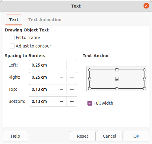
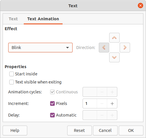
Figure 11: Text dialog - Text Animation page
1) Select a connector with text added and activate the control points to enter text mode. See “Adding text” above for more information on adding text to a connector.
2) Use the tools available on the Text Formatting toolbar or the options available in Format > Text on the Menu bar to format the text.
3) Right-click on the connector text and select Text from the context menu to open the Text dialog (Figure 10) and change how the text appears next to the connector. The options available are as follows:
Drawing Object Text – Fit to frame – resizes the text to fit the entire area of a connector rectangle or frame.
Drawing Object Text – Adjust to contour – adapts the text flow so that it matches the contours of the selected connector.
Spacing to Borders – specify the amount of space to leave between the connector and the borders of the text.
Text Anchor – select one of nine positions to anchor the text within the connector rectangle.
Full width – anchors the text to the full width of the connector rectangle. When selected, the top, middle and bottom center positions can be used for to anchor the text.
4) If required, click on Text Animation to open the Text Animation page (Figure 11) and access options to animate the text. However, this is not recommended unless the drawing is going to be displayed as part of a presentation. See the Impress Guide for more information on text animation.
5) Click OK to save the changes to text attributes and close the Text dialog.
6) Move the cursor away from text and connector, then click to end the text mode. This also closes the Text Formatting toolbar.
For drawing flowcharts (also known as flow diagrams), Draw has a floating Flowchart toolbar (Figure 12) that includes a large selection of flowchart tools to create a flowchart.
1) Click on the triangle ▼ to the right of Flowchart on the Drawing toolbar to open a Flowchart pop up menu. Note that the Flowchart icon changes shape depending on the last flowchart tool used.
2) Click at the top of the Flowchart pop-up menu and drag it into the Workspace.
3) Release the mouse button and the pop-up menu becomes a floating Flowchart toolbar.
Recommended basic steps to follow when creating a flowchart:
When adding objects or flowchart shapes to a flowchart, see Chapter 2, Drawing Basic Shapes for information on how to draw and resize object shapes.
Add text to each flowchart shape to make it easily identified in the flowchart. See Chapter 2, Drawing Basic Shapes and Chapter 11, Advanced Draw Techniques for more information.
Use connector lines in a flowchart. This allows repositioning of an object in a flowchart while maintaining connections with the other objects in the flowchart. See “Connectors and glue points” above for more information.
Use the zoom, grid, and snap functions to help in positioning objects in a flowchart. See Chapter 3, Working with Objects and Object Points for more information.
Use the alignment and distribution functions to give a flowchart a more professional look. See Chapter 5, Combining Multiple Objects for more information.
Duplicate objects when more than one of the same shape and size is required. See Chapter 5, Combining Multiple Objects for more information.
Figure 12: Flowchart sub-toolbar and available flowchart shapes
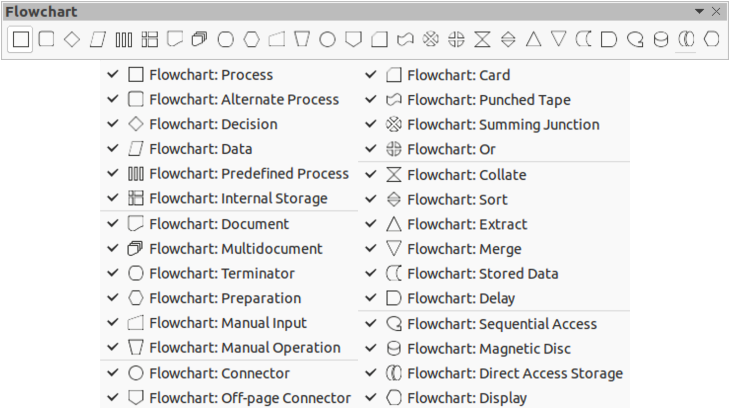
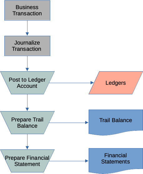
Figure 13: Example flowchart
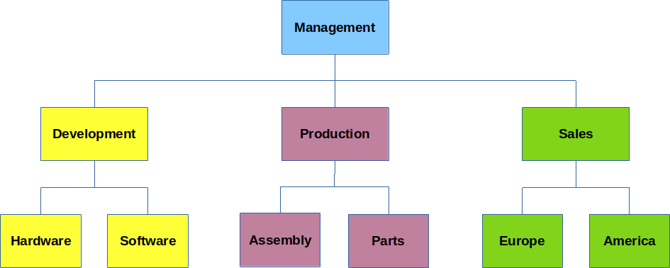
Draw does not have a toolbar for organization charts, but these charts are easily created using basic shapes, flowchart shapes, and connectors. Hierarchy in an organization is easily indicated using shading and/or color. When using shading and color in an organization chart, make sure the selection provides a good contrast between the text and the shading or color. This makes the chart easy to read on a computer display or in a printed document.
An example of an organization chart is shown in Figure 14. This was drawn using the rectangle basic shape and connectors.
1) When adding objects to a chart, see Chapter 2, Drawing Basic Shapes for information on how to draw and resize object shapes.
2) Add text to each object in the organization chart to make it easily identified in the chart. See Chapter 2, Drawing Basic Shapes and Chapter 11, Advanced Draw Techniques for more information.
3) Use connectors in an organization chart. This allows repositioning of an object in a chart while maintaining connections with the other objects in the chart. See “Connectors and glue points” above for more information.
4) Use the zoom, grid, and snap functions to help in positioning objects in a chart. See Chapter 3, Working with Objects and Object Points for more information.
5) Use the alignment and distribution functions to give an organization chart a more professional look. See Chapter 5, Combining Multiple Objects for more information.
6) Duplicate objects when more than one of the same shape and size is required. See Chapter 5, Combining Multiple Objects for more information.
Figure 14: Example of an organization chart