
Draw Guide 7.3
Chapter 4,
Changing Object Attributes
This document is Copyright © 2022 by the LibreOffice Documentation Team. Contributors are listed below. This document maybe distributed and/or modified under the terms of either the GNU General Public License (https://www.gnu.org/licenses/gpl.html), version 3 or later, or the Creative Commons Attribution License (https://creativecommons.org/licenses/by/4.0/), version 4.0 or later.
All trademarks within this guide belong to their legitimate owners.
|
Peter Schofield |
Kees Kriek |
|
|
Martin Fox |
Jean Hollis Weber |
John A Smith |
|
Hazel Russman |
John Cleland |
Peter Schofield |
|
Claire Wood |
Elzett Kotze |
|
Please direct any comments or suggestions about this document to the Documentation Team’s mailing list: documentation@global.libreoffice.org
Note
Everything sent to a mailing list, including email addresses and any other personal information that is written in the message, is publicly archived and cannot be deleted.
Published March 2022. Based on LibreOffice 7.3 Community.
Other versions of LibreOffice may differ in appearance and functionality.
Some keystrokes and menu items are different on macOS from those used in Windows and Linux. The table below gives some common substitutions for the instructions in this document. For a detailed list, see the application Help.
|
Windows or Linux |
macOS equivalent |
Effect |
|
Tools > Options on Menu bar |
LibreOffice > Preferences on Menu bar |
Access to setup options |
|
Right-click |
Ctrl+click and/or right-click depending on computer setup |
Opens a context menu |
|
Ctrl or Control |
⌘ and/or Cmd or Command |
|
|
Alt |
⌥ and/or Alt or Option |
Used with other keys |
|
F11 |
⌘+T |
Open the Styles deck in the Sidebar |
In LibreOffice the term Line indicates a freestanding segment (line), the outer edge of a shape (border), or an arrow. In most cases, the properties of the line that can be modified are its style (solid, dashed, invisible, and so on), its width, its color and the type of arrowhead.
Tip
Hovering the cursor over a tool icon on a toolbar or in the Sidebar, a pop up displays the name of the tool.
Note
For more information on using color when formatting lines, line styles, arrows, and arrow styles, see “Working with area fills” on page 1.
Format a line using the Line and Filling toolbar (Figure 1) as follows:
1) Make sure the line is selected in a drawing.
2) Select the line style required from the Line Style drop-down list.
3) Either type the line width in the Line Width text box, or use the up and down arrows to change the line width.
4) Click on the triangle ▼ to the right of Line Color and select a color from one of the available color palettes.
5) Click on the triangle ▼ to the right of Line Style and select a line style from one of the options in the drop-down list.
6) If necessary, select from the Arrow Style drop-down list the type of arrowhead for each end of the line and change the line into an arrow. The left drop-down list adds an arrow head to the beginning of the line. The right drop-down list adds an arrow head to the end of the line.
7) If necessary, click on Shadow to add a shadow to the line. The shadow applied uses the settings set in the Line dialog (Figure 26 on page 1).
8) Deselect the line to save the changes to the line.
Format a line using the Line panel in the Properties deck on the Sidebar (Figure 2) as follows:
1) Make sure the line is selected in a drawing.
2) Click on Properties on the Sidebar to open the Properties deck.
3) Click on Line to open the Line panel.
Figure 1: Line and Filling toolbar
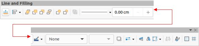
Figure 2: Line panel in Properties deck on Sidebar
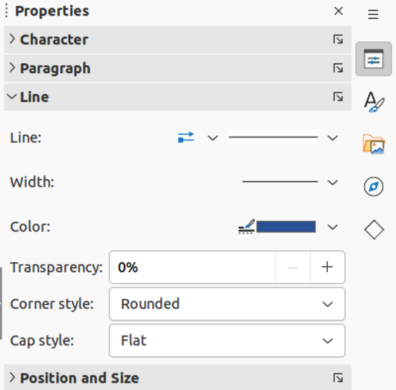
4) In Line, select from the Arrow Style drop-down lists the type of arrowhead for each end of the line and change the line into an arrow. The left drop-down list adds an arrowhead to the beginning of the line. The right drop-down list adds an arrowhead to the end of the line.
5) In Line, select the type of line required from the Line Style drop-down list.
6) In Width, select the line width from the Width drop-down list or enter a width in the Custom Line Width text box.
7) In Color, click on the triangle ▼ to the right of Line Color and select a color from one of the available color palettes.
8) In Transparency, enter a percentage for the amount of transparency for the line.
9) In Corner style, select a corner style from the drop-down list.
10) In Cap style, select a cap style from the drop-down list.
11) Deselect the line to save the changes to the line.
12) If necessary, click on More Options on the right of the title bar and open the Line dialog for more control over formatting lines.
To fully change the appearance of a line, use the Line dialog.
1) Make sure a line is selected on a slide.
2) Open the Line dialog (Figure 3) using one of the following methods:
Go to Format > Line on the Menu bar.
Right-click on the line and select Line from the context menu.
Click on More Options on the right of the Line panel title on the Sidebar.
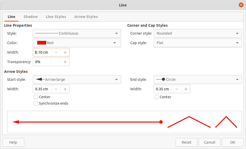
Figure 3: Line dialog - Line page
3) Use the options available in the pages of the Line dialog to format the line. The pages are Line, Shadow, Line Styles and Arrow Styles and the options available are explained in the following sections. A preview box at the bottom of the dialog shows the effect of the changes on a line.
4) Click OK to save the changes and close the dialog.
The Line page in the Line dialog is where the basic parameters of the line are set. It is divided into three sections as follows.
Line properties – this section sets the following parameters:
Style – select a line style from the drop-down list.
Color – select a predefined color from one of the available color palettes.
Width – specifies the thickness of the line.
Transparency – sets the transparency of a line. Figure 4 shows the effects of different percentages in transparency levels to lines when placed over an object.
Figure 4: Line transparency (0%, 25%, 50%, 75%)
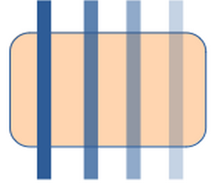
Figure 5: Default arrow top; centered arrow bottom
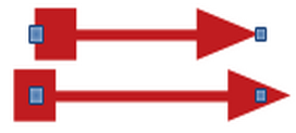
Arrow Styles – this section is only applicable to individual lines and is not used for lines that form the borders of an object.
Start style and End style – select from the drop-down list an arrow style or arrowhead for the start and end of a line.
Width – specifies the thickness of the arrow endings
Center – moves the center of the arrow endings to the end point of the line. Figure 5 shows the effects of selecting this option.
Synchronize ends – makes the two line ends identical.
Corner and Cap Styles – determines how the connection between two segments of a line looks. To appreciate the difference between these styles, choose a thick line style and observe how the preview changes.
Corner style – select the shape to be used at the corners of the line. For a small angle between lines, a mitered shape is replaced with a beveled shape.
Cap style – select the style of the line end caps. The caps are added to inner dashes as well.
The Shadow page (Figure 6) of the Line dialog provides the options to add and format a shadow to a selected line. The settings on this dialog page are the same as those for shadows applied to other objects, described in “Working with shadows” on page 1.
To quickly apply a shadow to a line, click on Shadow on the Line and Filling toolbar. Using the Shadow tool creates a shadow using the settings from the Shadow page in the Line dialog.
Figure 6: Line dialog - Shadow page
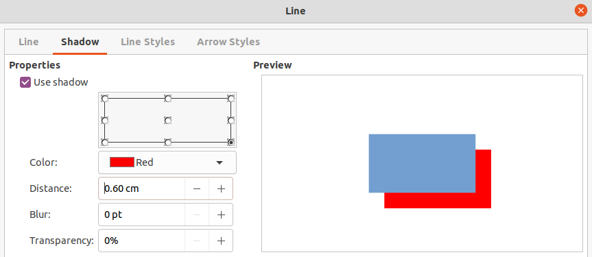
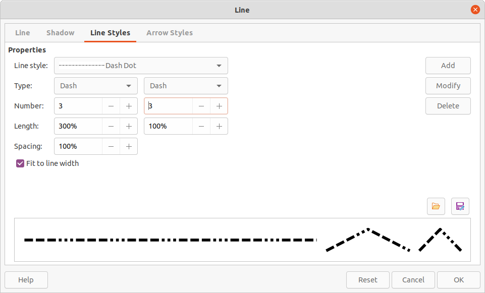
Figure 7: Line dialog - Line Styles page
Line styles are useful in a drawing when adding several lines of similar types reducing the need to format individual lines. LibreOffice provides standard line styles that can be used in a drawing. Also, line styles can be created, saved, and deleted.
The Line Styles page in the Line dialog (Figure 7) provides options to use predefined line styles and to create or change line styles.
1) Create a line in a drawing.
2) Open the Line dialog using one of the following methods:
Go to Format > Object and Shape > Line on the Menu bar.
Right-click on the line and select Line from the context menu.
3) Click on the Line Styles tab to open the Line Styles page.
4) In the Line style drop-down list, select a pre-defined line style similar to the style to be created. An example of the line style selected is displayed at the bottom of the dialog page. This example changes as changes are made to the line style.
5) In the Type drop-down menus, select either Dots or Dash.
To use only one type for the line, select the same type in both Type boxes.
To alternate the two line types within a single line, select different types in the two Type boxes.
6) In the Number boxes, specify the number of dots or dashes selected in Type. For different sized groups of dots or dashes, set a different quantity in each Number box.
7) In the Length boxes, specify the Dash length as a percentage of the line. The Length option is not available for Dots.
8) In the Spacing box, specify the spacing between the dashes and/or dots as a percentage of the line. The Spacing option is not available when the option Fit to line width is selected.
9) If necessary, select Fit to line width so that the new style fits the line width when that line is created in a drawing.
10) For the current document only, create a new line style, or modify a line style as follows:
a) Click on Add or Modify to open the Name dialog.
b) Enter a unique name for the new or modified line style.
c) Click on OK to save the new or modified line style and close the Name dialog.
11) Click on OK to close the Line dialog and the new line style is ready for use in the current drawing only.
Note
To use the new or modified line style in other drawings, the line style must be saved using Save Line Styles. See "Saving line styles" below for more information.
Note
When creating or modifying a line style, it is recommended to use a unique name for the line style. This prevents one of the standard line styles in LibreOffice from being overwritten and causing formatting problems in other drawings or documents that use the standard line styles.
Saving a line style allows for a newly created line style to be used in other LibreOffice drawings.
1) Create a new line style, described in “Creating line styles” above, but do not close the Line dialog.
2) Click on Save Line Styles at the bottom right of the Line Styles page to open a file browser window at the correct location for line styles.
3) Enter a unique filename using the file extension sod for the line style in the Name box.
4) Click on Save to save the line style and close the file browser window. The new line style is now available for use in new drawings and documents.
Standard line styles are provided when LibreOffice is installed on a computer. However, compatible line styles can loaded and used in LibreOffice. Any line styles loaded into LibreOffice must use the file extension sod.
1) Create a line in a drawing.
2) Open the Line dialog and click on the Line Styles tab to open the Line Styles page.
3) Click on Load Line Styles at the bottom right of the Line Styles page to open a file browser window at the correct location for line styles.
4) Select a style from the list of saved styles in the file browser window. The file extension for line styles is sod.
5) Click Open to load the line style into LibreOffice. The line style becomes available for other LibreOffice drawings and documents.
6) Click OK to close the Line dialog and save any changes made.
1) Open the Line dialog and click on the Line Styles tab to open the Line Styles page.
2) Select the line style for deletion from the Line style drop-down list.
3) Click on Delete and confirm the deletion by clicking on Yes in the confirmation dialog.
4) Click OK to close the Line dialog and save any changes made.
Note
When deleting line styles, make sure that the line style is not used in another document. It is recommended to only delete line styles that have been created and not to delete one of the LibreOffice predefined line styles. This prevents any formatting problems in other documents where the line style has been used.
Use the Arrow Styles page (Figure 8) in the Line dialog to create new arrow styles, modify existing arrow styles, or load previously saved arrow styles.
Any shape can be used as an arrowhead, but the shape must be convertible to a curve. A curve is something drawn without lifting a pencil. For example, a star can be converted to a curve, but a smiley face cannot.
1) Select a shape, or create a shape that can be converted to a curve for use as a new arrowhead. The part of the shape that is going to be point of the arrowhead must face upward. An example of a new arrowhead is shown in Figure 9.
Figure 8: Line dialog - Arrow Styles page
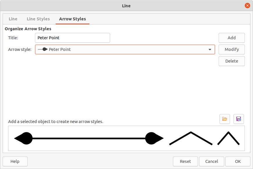
Figure 9: Example shape being used for an arrowhead

Note
The part of the shape being used as the point of the arrowhead must be at the top of the shape when creating a new arrowhead. If necessary, rotate the shape until the point is at the top of the shape.
2) Select the shape and convert to a curve using one of the following methods:
Right-click on the shape and select Convert > To Curve from the context menu.
Go to Shape > Convert > To Curve on the Menu bar.
3) With the shape selected, open the Arrow Styles page in the Line dialog.
4) Click on Add and type a unique name for the new arrow style in the Name dialog that opens, then click OK. The new arrowhead style is displayed in the preview box of the Line dialog and at the bottom of the Arrow style drop-down list.
5) Click OK to save the changes and close the Line dialog. The new arrow style is available only in the current document.
Note
Some shapes cannot be used as an arrowhead. This is indicated by rectangular blocks appearing at each end of the line in the preview box on the Line Styles page in the Line dialog.
Note
When creating an arrow style, it is recommended to use a unique name for the arrow style. This prevents one of the standard arrow styles in LibreOffice from being overwritten and causing formatting problems in other drawings that use the standard arrow styles.
Note
The new arrow style created is available only for use in the current drawing. To use the new arrow style in other drawings, the arrow style must be saved using the Save Arrow Styles option.
Saving an arrow style allows for the newly created style to be used in other LibreOffice documents.
1) Create a new arrow style as described in “Creating arrow styles” above, but do not close the Line dialog.
2) Click on the Save arrow styles icon at the bottom right of the Arrow Styles page to open a file browser window at the correct location for arrow styles.
3) Enter a unique filename using the file extension soe for the arrow style.
4) Click on Save to save the arrow style and close the file browser window. The new arrow style is now available for use in new documents.
LibreOffice provides standard arrow styles when installed on a computer. However, compatible arrow styles can be loaded and used in LibreOffice. Any arrow styles loaded into LibreOffice must use the file extension soe.
1) Open the Line dialog and click on the Arrow Styles tab to open the Arrow Styles page.
2) Click on the Load arrow styles icon at the bottom right of the Arrow Styles page to open a file browser window at the correct location for arrow styles.
3) Select an arrow style from the list of saved styles in the file browser window
4) Click Open to load the arrow style into the drawing. The arrow style also becomes available for other LibreOffice documents.
5) Click OK to close the Line dialog and save any changes made.
1) Open the Line dialog and click on the Arrow Styles tab to open the Arrow Styles page.
2) Select the arrow style for deletion from the Arrow style drop-down list.
3) Click on Delete and confirm the deletion by clicking on Yes in the confirmation dialog that opens.
4) Click OK to close the Line dialog and save any changes made.
Note
When deleting arrow styles, make sure that the arrow style is not used in another document. It is recommended to only delete arrow styles that have been created and not to delete one of the LibreOffice predefined arrow styles. This prevents any formatting problems in other documents where the arrow style has been used.
Area fill refers to the inside of an object that has an unbroken border, for example a rectangle, circle, star, pentagon and so on. An area fill can be none, a uniform color, gradient, hatching, bitmap or pattern, as shown in Figure 10. Also, an area fill can be made partly or wholly transparent and can throw a shadow.
Tools on the Line and Filling toolbar provide a range of default fills readily available to quickly format graphic objects. If this toolbar is not showing, go to View > Toolbars > Line and Filling on the Menu bar.
1) Select an object so that the selection handles are displayed.
2) Click on Area Style/Filling on the Line and Filling toolbar and select the type of fill required from the drop-down list.
None – select this option if an area fill for an object is not required.
Color (Figure 11) – select a color palette from the available options in the drop-down list, then select a color by clicking on the color.
Gradient (Figure 12) – select the required gradient from the drop-down list.
Hatching (Figure 13) – select the required hatching from the drop-down list.
Bitmap (Figure 14) – select the required bitmap from the drop-down list.
Pattern (Figure 15) – select the required pattern from the drop-down list.
3) Deselect the object to save the changes to the object.
Figure 10: Examples of area fill types
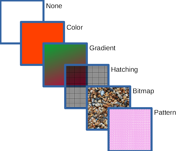
Figure 11: Color area fills
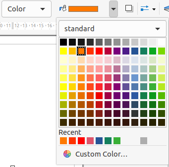
Figure 12: Gradient area fills
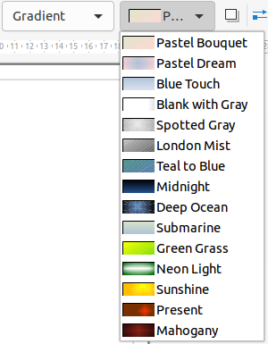
Figure 13: Hatching area fills
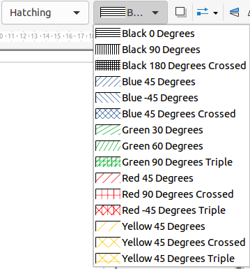
Figure 14: Bitmap area fills
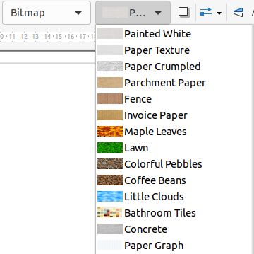
Figure 15: Pattern area fills
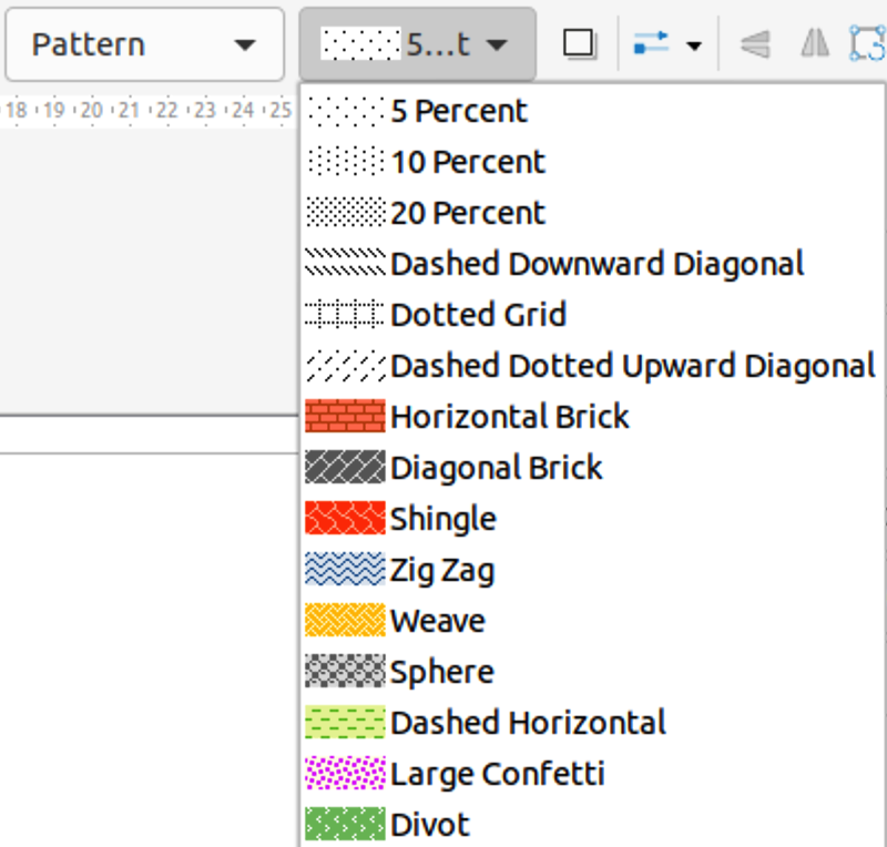
Figure 16: Area panel in Properties deck on Sidebar
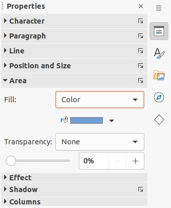
Format the area of an object using the Sidebar (Figure 16) as follows:
1) Make sure an object with an area fill is selected in a drawing.
2) Click on Properties on the Sidebar, then click on the down arrowhead ˅ on the left of the Area titlebar to open the Area panel.
3) Use the options in the Fill and Transparency drop-down lists to format the area of an object.
4) Deselect the object to save the changes.
Figure 17: Area dialog - Area Color page
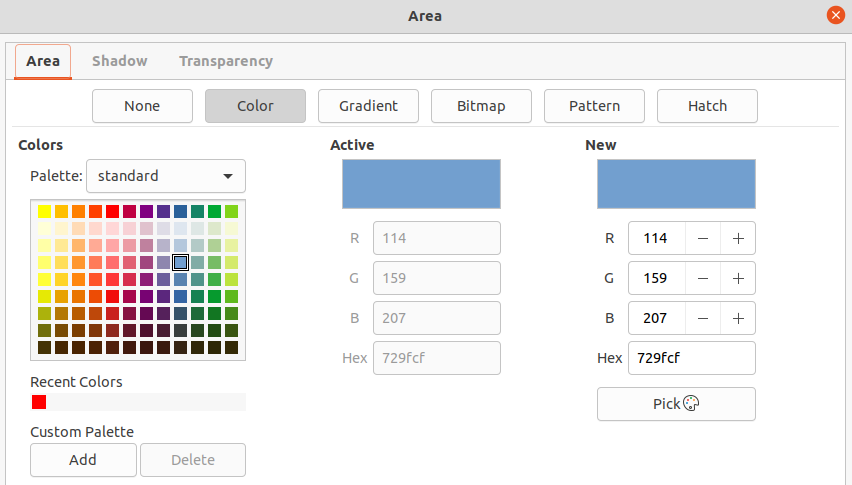
Format area fills with greater control using the Area dialog (Figure 17) as follows:
1) Make sure the object is selected in a drawing.
2) Open the Area dialog using one of the following methods:
Go to Format > Area on the Menu bar.
Click on Area in the Line and Filling toolbar.
Right-click on the selected object and select Area from the context menu.
Click on More Options on the right of the Area section title on the Sidebar.
3) Click on the Area tab to open the Area page.
4) Select the type of area fill from the available options (None, Color, Gradient, Bitmap, Pattern, or Hatch)
5) Select the style of area fill from the options that become available for each type of area fill selected.
6) Click OK to close the Area dialog and save the changes.
The following procedure to select a color for an area fill uses the Area dialog. Using the tools on the Line and Filling Toolbar, and the Area panel in the Properties deck on the Sidebar is a similar procedure, but the available options are reduced. All color fills are solid colors.
1) Make sure the object is selected in a drawing.
2) Open the Area page on the Area dialog, then click on Color to open the options available for a color fill.
3) In Colors, select the required palette from the available options in the Palette drop-down list.
4) Click on the color required. All color fills available are solid colors.
Active preview box shows the present color fill of a selected object. After selecting a color, a preview of the selected color appears in the New preview box.
Alternatively, enter the RGB or Hex values of a color in the appropriate text box.
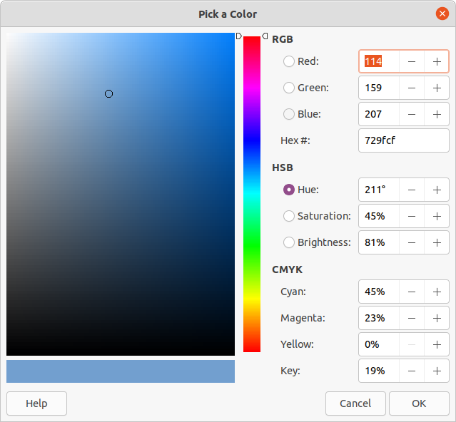
Alternatively, click on Pick to open the Pick a Color dialog (Figure 18). Select a color from the color box or enter the RGB, Hex, HSB or CMYK values for the color required.
If a color has been used before, then select the required color from those available in Recent Colors.
5) If necessary and to revert back to the original color, click on Reset and any changes made are removed.
6) Click OK to close the Area dialog and save the changes. The color area fill is then changed in the selected object.
1) Select a filled object to create a color.
2) Open the Area dialog and click on Area to open the Area page, then click on Color to open the options available for a color fill.
3) Specify the values of Red (R), Green (G), and Blue (B) on a 0 to 255 scale, or the percentages of Cyan (C), Magenta (M), Yellow (Y), and Black (K) to create a new color.
Figure 18: Pick A Color dialog
4) Click on Add in Custom Palette and enter a name for the color in the Name dialog that opens.
5) Click OK to close the Name dialog and the color is added to the Custom palette.
6) Click OK to close the Area dialog and save the changes. The new custom color appears as a fill in the selected object and is available for use in other drawings or documents.
1) Select a filled object to create a color.
2) Open the Pick a Color dialog (Figure 18) using one of the following methods:
Click on Pick on the Colors page of the Area dialog.
Click on the triangle ▼ next to Fill Color on the Line and Filling toolbar and select Custom Color.
Click on the triangle ▼ next to Fill Color in the Area section of the Properties deck on the Sidebar and select Custom Color.
3) Create a custom color using one of the following methods. A preview of the color created is shown in the colored box below the original color on the left side of the dialog.
Select a color range from the colored bar, then, using the cursor, move the target in the colored box until the cursor is on the color required.
Enter values for Red (R), Green (G), and Blue (B) in the RGB text boxes.
Enter values for Cyan (C), Magenta (M), Yellow (Y), and Key (K) (black) in the CMYK text boxes.
Enter values for Hue (H), Saturation (S), and Brightness (B) in the HSB text boxes. HSB values do not change the color, but how a color looks.
If known, enter the Hex# number in the text box. For example, Hex numbers are normally used when a specific color has been created for a company logo or company name.
Note
Changing one set of color values also changes the color values in the other sets.
4) Click OK to close the Pick a Color dialog and save the changes.
5) Click on Add in Custom Palette and enter a name for the color in the Name dialog that opens.
6) Click OK to close the Name dialog and the color is added to the Custom palette.
7) Click OK to save the changes and close the Area dialog. The new color appears as a fill in the selected object and is available for use in other drawings or documents.
1) Select a filled object that uses the color fill for deletion.
2) Open the Area dialog using one of the following methods:
Go to Format > Area on the Menu bar.
Right-click on the object and select Area from the context menu.
Click on More Options on the right of the Area section title on the Sidebar.
3) Click on Area, then click on Colors to open the Colors page.
4) In Colors, select Custom from the Palette drop-down list.
5) Select the color for deletion and click on Delete. There is no confirmation given when deleting a color.
6) Click OK to save the changes and close the Area dialog.
Note
Only custom colors that are available in the custom palette can be deleted using the Area dialog. Colors that are available in the color palettes provided by LibreOffice cannot be deleted.
Several predefined gradients are included when LibreOffice is installed. It is recommended to create custom gradients that match the requirements rather than modifying the installed predefined gradients. Predefined gradients may have been used in other objects in a drawing or other documents.
Custom gradients are saved with a unique name allowing the custom gradient to be used in other drawings or documents. Custom gradients are placed at the end of the gradients displayed in the Gradient box on the Gradient page of the Area dialog (Figure 19).
The following procedure to select a gradient for an area fill uses the Area dialog. Using the tools on the Line and Filling Toolbar, and the Area panel in the Properties deck on the Sidebar is a similar procedure, but the available options are reduced.
1) Make sure the object to be filled is selected in a drawing.
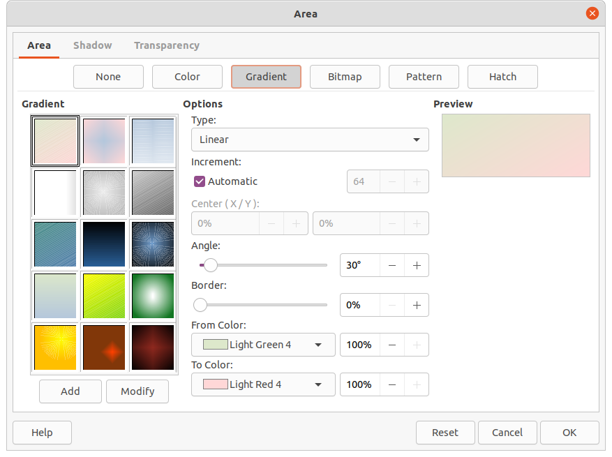
Figure 19: Area dialog – Area Gradient page
2) Open the Area dialog and click on Area to open the Area page, then click on Gradient to open the options available for a gradient fill.
3) In Gradient, select the required gradient from the list of available gradients and the gradient appears in Preview.
4) To override the default gradient transition of a selection, deselect Automatic in Options and then enter the values for Type, Increment, Center, Angle, Border, From Color and To Color to modify the gradient to the requirements. As changes are made, the gradient displayed in Preview also changes to indicate how the gradient will look. For more information on gradient options, see “Table 1: Gradient options” below.
5) Click OK to close the Area dialog and save the changes. The gradient area fill then appears in the selected object.
Note
Selecting and modifying a gradient using the above method only allows the gradient to be used in the drawing being created. If a modified gradient is to be used in other drawings or documents, then create a custom gradient and save it with a unique name. See “Creating custom gradients” below.
Table 1: Gradient options
|
Gradient property |
Meaning |
|
Linear gradient |
The color transitions from the starting color to the end color in a straight line. |
|
Axial gradient |
The color transitions from the starting color to the end color from the object center to the object edges in two opposite directions. |
|
Radial gradient |
The color transitions from the starting color to the end color in a circular pattern. |
|
Ellipsoid gradient |
The color transitions from the starting color to the end color in an elliptical pattern. |
|
Quadratic gradient |
The color transitions from the starting color to the end color from the object edges to the object center in four directions. |
|
Square gradient |
The color transitions from the starting color to the end color from the object edges to the object center in a square pattern. |
|
Increment |
Enter the number of steps for blending the two colors of the gradient. By default this is set to Automatic. |
|
Center X |
For Radial, Ellipsoid, Square and Rectangular gradients, modify these values to set the horizontal offset of the gradient center. |
|
Center Y |
For Radial, Ellipsoid, Square and Rectangular gradients, modify these values to set the vertical offset of the gradient center. |
|
Angle |
For all gradient types, modifies the angle of the gradient axis. |
|
Border |
Increase this value to make the gradient start further away from the border of the shape. |
|
From Color |
The start color for the gradient. In the edit box enter the intensity of the color: 0% corresponds to black, 100% to the full color. |
|
To Color |
The end color for the gradient. In the edit box enter the intensity of the color: 0% corresponds to black, 100% to the full color. |
To use a modified gradient in other drawings or documents, a custom gradient has to be saved with a unique name.
1) Make sure the object is selected in a drawing.
2) Open the Area dialog and click on Area to open the Area page, then click on Gradient to open the options available for a gradient fill.
3) Select a gradient and modify it using the options given in “Table 1: Gradient options” above. As changes are made, the gradient displayed in Preview also changes to give an indication of how the modified gradient will look.
4) Click on Add to open a Name dialog.
5) Enter a unique name for the new gradient, then click OK to close the Name dialog. The custom gradient is placed at the end of the gradients displayed in Gradient and becomes available for use in other drawings and documents.
6) Click OK to close the Area dialog and save the changes.
1) Make sure the object is selected in a drawing.
2) Open the Area dialog and click on Area to open the Area page, then click on Gradient to open the options available for a gradient fill.
3) Select a custom gradient in Gradient. Custom gradients appear below the predefined gradients in Gradient.
4) Enter the new values for the gradient options that need to be changed. See “Table 1: Gradient options” above for more information on gradient options. Depending on the type of gradient selected, some options may not be available.
5) If necessary and to revert back to the original gradient, click on Reset and any changes made are removed.
6) Click on Modify to permanently change the selected custom gradient. There is no confirmation given when modifying a custom gradient.
7) Click OK to close the Area dialog and save the changes.
Note
Using the Modify option on the Gradient page in the Area dialog permanently changes a gradient and cannot be undone. It is recommended to only modify custom gradients and not the predefined gradients that were installed with LibreOffice.
1) Select the object that uses the gradient that is going to be renamed.
2) Open the Area dialog and click on Area to open the Area page, then click on Gradient to open the options available for a gradient fill.
3) Right-click on the gradient and select Rename from the context menu.
4) Enter a name for the gradient in the Name dialog that opens.
5) Click OK save the change and close the Name dialog.
6) Click OK to save the changes and close the Area dialog.
1) Select an object that uses a gradient fill.
2) Open the Area page on the Area dialog, then click on Gradient.
3) In the Gradient box, select the custom gradient for deletion.
4) Right click on the gradient and select Delete from the context menu. Click on Yes to confirm the deletion.
5) Click OK to save the changes and close the Area dialog.
Note
It is recommended to only delete or rename custom gradients that have been created. Deleting or renaming one of the predefined gradients that are installed with LibreOffice may cause problems in drawings and documents that use one of the gradients.
LibreOffice provides advanced controls for gradients on the Transformations toolbar (Figure 20).
1) Make sure the object is selected in a drawing.
2) Open the Area page on the Area dialog, then click on Gradient.
3) Go to View > Toolbars > Transformations on the Menu bar or click on the Transformations tool on the Line and Filling toolbar to open the Transformations toolbar.
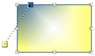
4) Click on Interactive gradient tool in the Transformations toolbar. This displays a dashed line connecting two colored squares (Figure 21). The colors show the From Color and To Color that are used for the selected gradient.
5) Select the type of gradient required for the object from the options in the Type drop-down list. Properties available for adjustment depend on the gradient type selected, as explained below. Moving the squares has different effects depending on the type of gradient.
Linear – move From Color square to change where the gradient starts (border value). Move the To Color square to change the orientation (angle value).
Axial – move the To Color square to change both the angle and border properties of the gradient. Only the To Color square can be moved.
Radial – move the From Color square to modify the border property to set the width of the gradient circle. Move the To Color square to change the point where the gradient ends (Center X and Center Y values).
Figure 20: Transformations toolbar
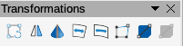
Figure 21: Example of using Interactive Gradient tool
Ellipsoid – move the From Color square to modify the border property to set the size of the gradient ellipsoid. Move the To Color square to change the angle of the ellipsoid axis and the axis itself.
Quadratic – move the From Color square to modify the border property to set the size of the gradient square or rectangle and the angle of the gradient shape. Move the To Color square to change the center of the gradient.
Square – move the From Color square to modify the border property to set the size of the gradient square or rectangle and the angle of the gradient shape. Move the To Color square to change the center of the gradient.
6) Click OK to save the changes and close the Area dialog.
Note
Moving the squares creates different effects depending on the type of gradient. For example, for a linear gradient, the start and end squares of the gradient are always situated either side of the center point of the object.
Several predefined bitmaps are included when LibreOffice is installed on a computer. The content of the supplied bitmaps cannot be edited, but the display settings can be changed. Also, bitmaps can be imported from other sources. A GIF is an example of a graphics image file that has a bitmap.
Figure 22: Area dialog – Area Bitmap page
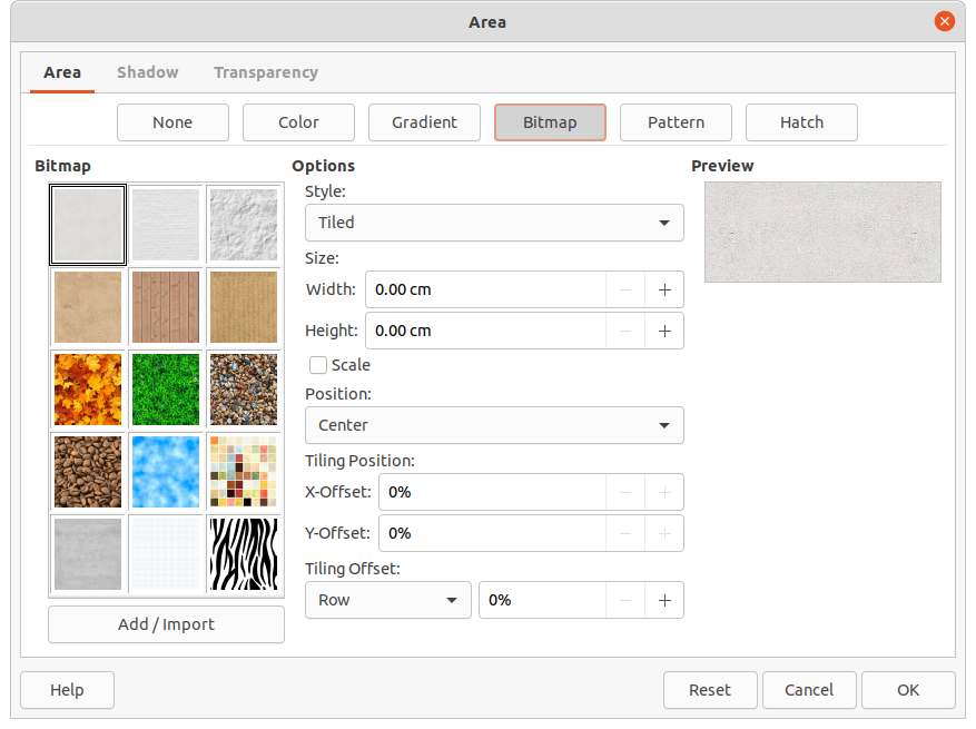
Table 2: Bitmap options
|
Bitmap option |
Meaning |
|
Style – Custom position/size |
When this option is selected, the position of the bitmap in the object and the size of the bitmap can be specified. |
|
Style – Tiled |
When this option is selected, the bitmap is tiled to fill the area. The size of the bitmap used for the tiling is determined by the Size settings |
|
Style – Stretched |
When this option is selected, a bitmap is stretched to fill the object area. |
|
Size – Width |
Sets the width of the bitmap. For example, 100% means that the bitmap is resized to occupy the whole fill area width, 50% means that the width of the bitmap is half that of the fill area. |
|
Size – Height |
Sets the height of the bitmap. For example, 100% means that the bitmap is resized to occupy the whole fill area height, 50% means that the height of the bitmap is half that of the fill area. |
|
Size – Scale |
When selected, bitmap size is given as a percentage for Width and Height. When deselected, the actual size of the bitmap is given for Width and Height. |
|
Position |
Specifies the anchoring point of the bitmap. |
|
Tiling Position – X-Offset |
Sets the offset for the width of the bitmap in percentage values. 50% offset means that Draw will place the middle part of the bitmap width at the anchor point and start tiling from there. |
|
Tiling Position – Y-Offset |
Sets the offset for the height of the bitmap in percentage values. 50% offset means that Draw will place the middle part of the bitmap height at the anchor point and start tiling from there. |
|
Tiling Offset |
Offsets the columns of tiled bitmaps by the percentage entered in the box so that two subsequent columns of bitmaps are not aligned. |
The following procedure to select a bitmap for an area fill uses the Bitmap page of the Area dialog (Figure 22). Using the tools on the Line and Filling Toolbar, and the Area panel in the Properties deck on the Sidebar is a similar procedure, but the available options are reduced.
1) Make sure the object is selected in a drawing.
2) Open the Area dialog and click on Area to open the Area page, then click on Bitmap to open the options available for a bitmap fill.
3) In Bitmap, select the required bitmap from the list of available bitmaps and it appears in Preview. Alternatively, click on Add/Import to open a file browser window, then select a file to use as a bitmap fill.
4) If necessary, change the values in Style, Size, Position, Tiling Position, and Tiling Offset to modify the bitmap to the requirements. For more information on bitmap options, see “Table 2: Bitmap options” above.
5) If necessary and to revert back to the original bitmap, click on Reset and any changes made are removed.
6) Click OK to close the Area dialog and save the changes. The bitmap fill then appears in the selected object.
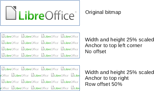
Figure 23: Examples of bitmap fills
1) Select an object for editing that contains a bitmap as a fill, or insert a bitmap into a selected object
2) Open the Area dialog and click on Area to open the Area page, then click on Bitmap to open the options available for a bitmap fill.
3) Select a bitmap from the options available in Bitmap to use and edit as a fill. Note that any imported bitmaps are also available. The selected bitmap appears in Preview. Note that any imported bitmaps are also available.
4) Change the values for Style, Size, Position, Tiling Position, and Tiling Offset to the requirements. For more information on bitmap options, see “Table 2: Bitmap options” above. Examples of bitmap fills and the properties used are shown in Figure 23.
5) If necessary and to revert back to the original bitmap, click on Reset and any changes made are removed.
6) Click OK to save the changes and close the Area dialog.
Note
Supplied bitmaps cannot be edited, but the display settings for placement and tiling can be changed.
1) Select an object to import a bitmap into the object.
2) Open the Area dialog and click on Area to open the Area page, then click on Bitmap to open the options available for a bitmap fill.
3) Click on Add/Import and a file browser window opens.
4) Navigate to the directory containing the bitmap file, then select the file and click Open.
5) Enter a unique name for the new bitmap in the Name dialog that opens, then click OK to close the Name dialog. The imported bitmap appears at the bottom of the bitmaps displayed in Bitmap.
6) Select the imported bitmap in Bitmap.
7) Click OK to save the changes and close the Area dialog. The imported bitmap fill appears in the selected object.
1) Select an object that uses a bitmap.
2) Open the Area dialog and click on Area to open the Area page, then click on Bitmap to open the options available for a bitmap fill.
3) Right-click on the bitmap selected for renaming and select Rename from the context menu.
4) Enter a new name for the bitmap in the Name dialog that opens.
5) Click OK to save the change and close the Name dialog.
6) Click OK to save the changes and close the Area dialog.
1) Make sure the object containing a bitmap fill is selected in a drawing.
2) Open the Area page on the Area dialog, then click on Bitmap.
3) Right click on the bitmap being deleted and select Delete from the context menu. Click on Yes to confirm the deletion.
4) Click OK to save the changes and close the Area dialog.
Note
It is recommended to only rename or delete bitmaps that have been created or imported. Renaming or deleting bitmaps that are installed with LibreOffice may cause problems in documents that use one of these bitmaps.
Several predefined pattern fills are included when LibreOffice is installed on a computer. Custom patterns can also be created and modified in LibreOffice.
The following procedure to select a pattern for an area fill uses the Area dialog. Using the tools on the Line and Filling Toolbar, and the Area panel in the Properties deck on the Sidebar is a similar procedure, but the available options are reduced.
1) Make sure the object is selected in a drawing.
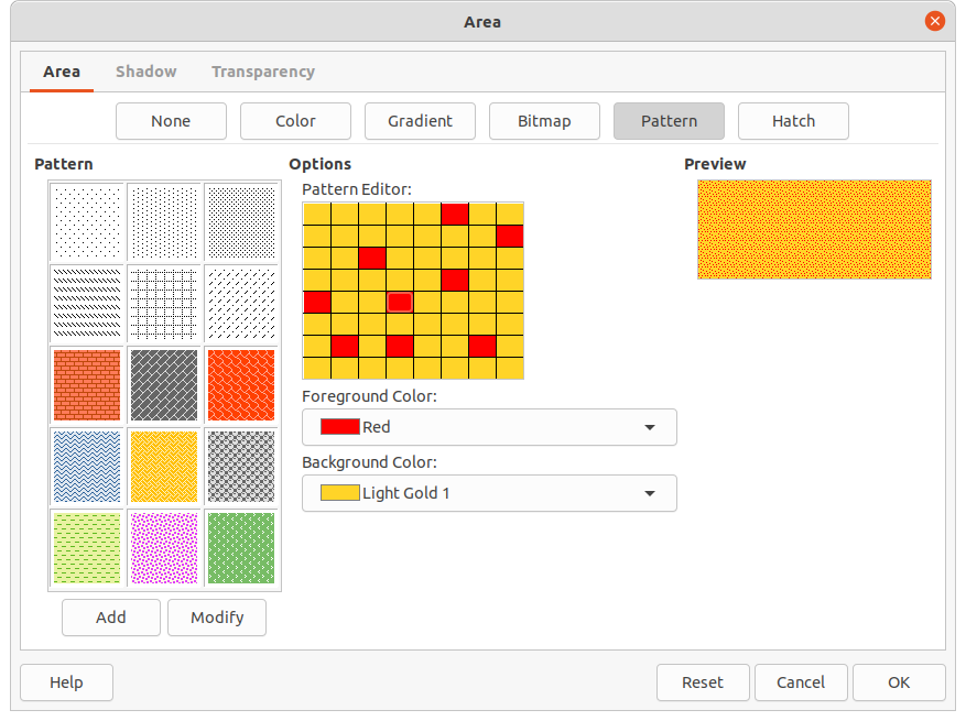
2) Open the Area dialog and click on Area to open the Area page, then click on Pattern to open the options available for a pattern fill (Figure 24).
3) In Pattern, select the required pattern and the selected pattern appears in Preview.
4) If necessary, change the foreground and background colors, or the pattern itself, as described in “Creating custom patterns” below. As changes are made, the pattern displayed in Preview also changes to indicate how the pattern will look. Any changes will affect only the object being filled.
5) If necessary and to revert back to the original pattern, click on Reset and any changes made are removed.
6) Click OK to close the Area dialog and save the changes. The pattern fill then appears in the selected object.
1) Make sure the object is selected in a drawing.
2) Open the Area dialog and click on Area to open the Area page.
Figure 24: Area dialog – Area Pattern page
3) Select the required pattern in Pattern to use as a starting point and the selected pattern appears in Preview.
4) In Options, select a color from the available color palettes for the Foreground Color and Background Color. The pattern remains the same, but the colors change.
5) In Pattern Editor, click on individual squares to change the color from Foreground Color to Background Color, or from Background Color to Foreground Color to create a new pattern.
6) In Preview, check the pattern being created to see if the desired effect is being achieved.
7) Click on Add to open a Name dialog.
8) Enter a unique name for the new pattern, then click OK to close the Name dialog. The custom pattern is placed at the end of the patterns displayed in Pattern and becomes available for use in other drawings and documents.
9) If necessary and to revert back to the original pattern, click on Reset and any changes made are removed.
10) Click OK to close the Area dialog and save the changes.
Note
To use a modified pattern in other drawings or documents, the custom pattern has to be saved with a unique name.
Using the Modify option on the Pattern page in the Area dialog permanently changes a pattern and cannot be undone. It is recommended to only modify custom patterns and not the predefined patterns that were installed with LibreOffice.
1) Make sure the object is selected in a drawing.
2) Open the Area dialog and click on Area to open the Area page, then click on Pattern.
3) Select a custom pattern from the patterns displayed in Pattern and the selected pattern appears in Preview. Custom patterns are located below the predefined patterns in the Pattern.
4) In Pattern Editor, click on each square to change the color from Foreground Color to Background Color, or from Background Color to Foreground Color to modify the selected pattern.
5) If necessary and to revert back to the original pattern, click on Reset and any changes made are removed.
6) Click on Modify to permanently change the selected custom pattern. There is no confirmation given when modifying a custom pattern.
7) Click OK to close the Area dialog and save the changes.
1) Select an object that contains a pattern, or insert a pattern into the selected object.
2) Open the Area dialog and click on Area to open the Area page, then click on Pattern to open the options available for a pattern fill. The selected pattern appears in Pattern Editor.
3) Right-click on the pattern for renaming in Preview and select Rename from the context menu.
4) Enter a name for the pattern in the Name dialog that opens.
5) Click OK to save the renaming and close the Name box.
6) Click OK to save the changes and close the Area dialog.
1) Select an object that contains a pattern, or insert a pattern into the selected object.
2) Open the Area dialog and click on Area to open the Area page, then click on Pattern to open the options available for a pattern fill. The selected pattern appears in Pattern Editor.
3) Right-click on the pattern for deletion in the Preview box and select Delete from the context menu.
4) Click on Yes to confirm the deletion.
5) Click OK to save the changes and close the Area dialog.
Note
It is recommended to only modify, delete or rename custom patterns that have been created. Deleting or renaming one of the predefined patterns that are installed with LibreOffice may cause problems in drawings and documents that use one of the gradients.
Figure 25: Area dialog – Area Hatch page
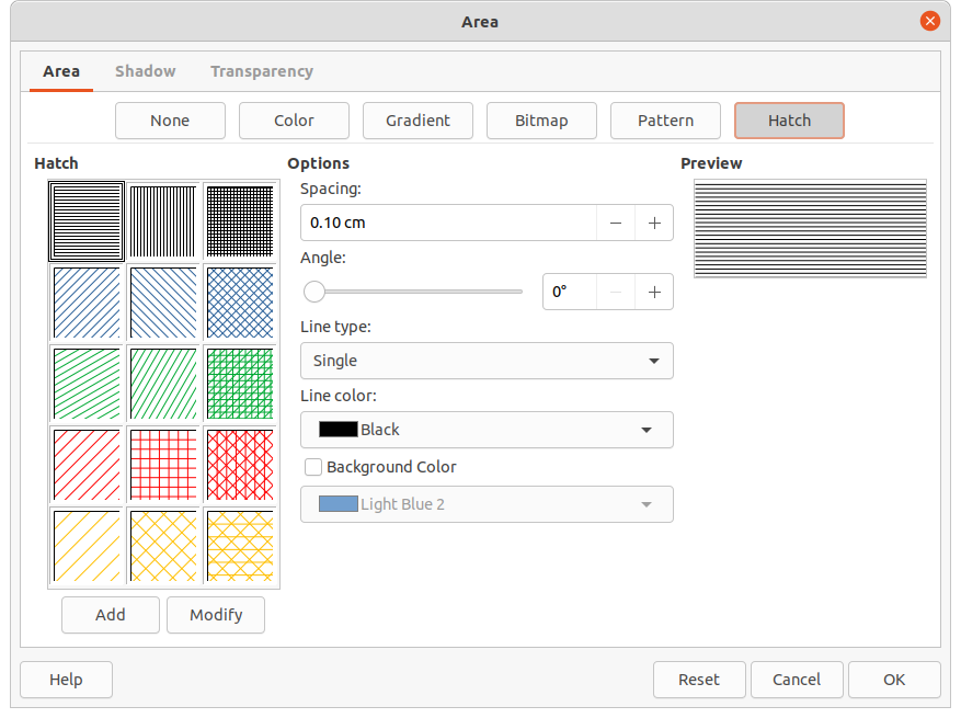
Hatchings fills are similar to pattern fills, but use lines instead of squares. Several predefined hatching fills are included when LibreOffice is installed on a computer. Custom hatching fills can also be created and modified.
The following procedure to select a hatching for an area fill uses the Area dialog. Using the tools on the Line and Filling Toolbar, and the Area panel in the Properties deck on the Sidebar is a similar procedure, but the available options are reduced.
1) Make sure the object is selected in a drawing.
2) Open the Area dialog and click on Area to open the Area page, then click on Hatch to open the options available for a hatch fill (Figure 25).
3) Select a hatch from the options shown in Hatch and the selected hatch appears in the Preview.
4) If necessary, change the colors or other options, as described in “Creating custom hatching” below. As changes are made, the hatching displayed in Preview also changes.
5) If necessary and to revert back to the original hatching, click on Reset and any changes made are removed.
6) Click OK to close the Area dialog and save the changes. The hatching fill then appears in the selected object.
1) Make sure the object is selected in a drawing.
2) Open the Area dialog and click on Area to open the Area page, then click on Hatch to open the options available for a hatch fill.
3) Select the required hatching in Hatch as a starting point and the selected hatching appears in Preview.
4) Change the values for Spacing, Angle, Line type, Line color, and Background color to edit the hatching to the requirements. For more information on hatching options, see “Table 3: Hatching options” below.
5) Click on Add to open a Name dialog.
6) Enter a unique name for the new hatching, then click OK to close the Name dialog. The custom hatching is placed at the end of the hatchings displayed in Hatch and becomes available for use in other drawings and documents.
7) Click OK to close the Area dialog and save the changes. The new hatch fill appears in the selected object.
Table 3: Hatching options
|
Hatching option |
Meaning |
|
Spacing |
Determines the spacing between two lines of the hatching fill. As the value is changed, the preview window is updated. |
|
Angle |
Use the mini map below the numerical value to quickly set the angle formed by the line to multiples of 45 degrees. If the required angle is not a multiple of 45 degrees, enter the desired value in the edit box. |
|
Line type |
Set single, double, or triple line for the style of the hatching. |
|
Line color |
Use the list to select the color of the lines that will form the hatching. |
|
Background color |
When selected, adds a color fill behind the lines used for the hatching. |
Using the Modify option on the Hatch page in the Area dialog permanently changes a hatching and cannot be undone.
1) Make sure the object is selected in a drawing.
2) Open the Area dialog and click on Area to open the Area page, then click on Hatch to open the options available for a hatch fill.
3) Select a custom hatching in Hatch and the selected hatching appears in Preview. Custom hatchings are located below the predefined hatchings in Hatch.
4) Change the values for Spacing, Angle, Line type, Line color, and Background color to edit the hatching. For more information on hatching options, see “Table 3: Hatching options” above.
5) If necessary and to revert back to the original hatching, click on Reset and any changes made are removed.
6) Click on Modify to permanently change the selected custom hatching. There is no confirmation given when modifying a custom hatching.
7) Click OK to close the Area dialog and save the changes.
1) Select the object that contains the hatch fill that is to be renamed.
2) Open the Area dialog and click on Area to open the Area page, then click on Hatch to open the options available for a hatch fill.
3) Right-click on the hatch fill displayed in Hatch and select Rename from the context menu.
4) Enter a name for the hatch fill in the Name dialog that opens.
5) Click OK to save the renaming and close the Name dialog.
6) Click OK to save the changes and close the Area dialog.
1) Select an object that uses the hatching fill for deletion.
2) Open the Area page on the Area dialog, then click on Hatch.
3) In the Hatch box, select the custom hatching for deletion.
4) Right-click on the hatching and select Delete from the context menu. Click on Yes to confirm the deletion.
5) Click OK to save the changes and close the Area dialog.
Note
It is recommended to only modify, rename or delete hatch fills that have been created. Modifying, renaming or deleting hatch fills that were installed with LibreOffice may cause problems in documents that use one of these hatch fills.
Shadows can be applied to objects such as lines, shapes and text. The options available for shadows are as follows:
Position – select one of nine points determining the direction in which the shadow is cast.
Distance or Angle – determines the offset distance between the object and the shadow.
Color – sets the color used for the shadow.
Blur – sets how much the edges of a shadow are blurred or softened.
Transparency – determines the amount of transparency for the shadow: 0% opaque shadow, 100% transparent shadow.
To quickly apply a shadow to an object, select the object and click on Shadow in the Line and Filling toolbar. The shadow applied to an object using this method is set to the default shadow settings in LibreOffice.
Note
For more control when applying shadows, use the Shadow page in Area or Line dialogs. The following information describes the use of the Shadow page in the Area dialog (Figure 26), but can also be applied to the Shadow page in the Line dialog.
Figure 26: Area dialog - Shadow page
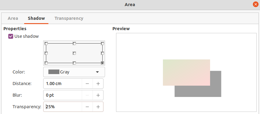
For a more control when adding shadows to an object, use the Shadow page on the Area dialog (Figure 26) as follows:
1) Select an object where a shadow is going to be applied.
2) Open the Area dialog and click on Shadow to open the Shadow page.
3) Select Use shadow in Properties and the shadow options become active.
4) Select from one of nine points the direction in which the shadow is going to be cast in relation to the object.
5) In Color, select the color palette from the drop-down list of available palettes and then select the color required for the shadow.
6) In Distance, enter a distance to set spacing between the object and the shadow.
7) In Blur, enter a value to soften the edges of the shadow.
8) In Transparency, enter a percentage for the shadow transparency.
9) Click OK to close the Area dialog and save the changes.
1) Select an object where a shadow is going to be applied.
2) Click on Properties to open the Properties deck on the Sidebar.
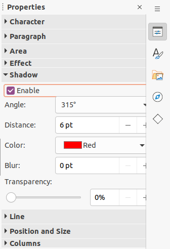
3) Click on Shadow to open the Shadow panel (Figure 27) in the Properties deck.
4) Select Enable and the shadow options become active.
5) In Angle, select from one of the options available from the drop-down list to set the direction of where the shadow is going to be cast in relation to the object.
6) In Color, select the color palette from the drop-down list of available palettes and then select the color required for the shadow.
7) In Distance, enter a distance to set spacing between the object and the shadow.
8) In Blur, enter a value to soften the edges of the shadow.
9) In Transparency, move the slider or enter a percentage in the text box to set the shadow transparency.
10) Deselect the object to save the changes made.
Figure 27: Shadow panel in Properties on sidebar
Transparencies can be applied to objects and to any shadow that has been applied to an object. In Draw two types of transparencies can be applied to an object – uniform transparency and gradient transparency. For more information on gradient transparencies, including an example of combining a color gradient with a gradient transparency, see “Gradient fills” on page 1.
Transparencies can be applied to area fills as well as shadows and lines.
To use transparencies on lines, refer to “Formatting lines” on page 1 for more information.
To use transparencies on shadows, refer to “Working with shadows” on page 1 for more information.
The following procedure applies a transparency to an object area fill using the Area dialog (Figure 28):
1) Make sure the object is selected in a drawing.
2) Open the Area dialog, then click on Transparency to the open the Transparency page and access the available options.
3) To create a uniform transparency, select Transparency and enter a percentage in the text box.
4) To create a gradient transparency so that the area becomes gradually transparent, select Gradient and select the type of gradient transparency from the drop-down list: Linear, Axial, Radial, Ellipsoid, Quadratic or Square. See “Table 1” on page 1 for more information on gradient types.
Figure 28: Area dialog - Transparency page
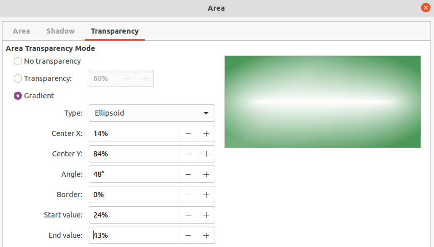
5) Set the parameters for the type of the gradient transparency selected above. Refer to “Table 4: Transparency parameters” below for a description of the properties. The parameters available depends on the type of gradient transparency selected above.
6) Click OK to close the Area dialog and save the changes.
Table 4: Transparency parameters
|
Transparency parameters |
Meaning |
|
Centre X |
For Radial, Ellipsoid, Quadratic and Square gradients. The values to set the horizontal offset of the gradient center. |
|
Center Y |
For Radial, Ellipsoid, Quadratic and Square gradients. The values to set the vertical offset of the gradient center. |
|
Angle |
For Linear, Axial, Ellipsoid, Quadratic and Square gradients. Specifies the angle of the gradient axis. |
|
Border |
Increase this value to make the gradient start further away from the border of the object. |
|
Start value |
Value for the starting transparency gradient. 0% is fully opaque, 100% means fully transparent. |
|
End value |
Value for the ending transparency gradient. 0% is fully opaque, 100% means fully transparent. |
Suppose that the same area fill, line thickness, and border is to be applied to a set of objects. This repetitive process can be greatly simplified by the use of styles. Styles allow a format to be defined and then applied to multiple objects. For more information on creating styles, see the Writer Guide.
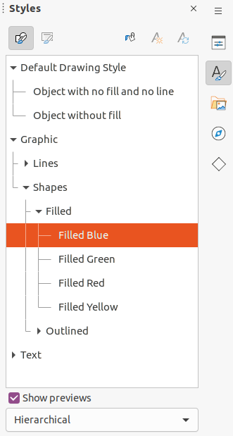
Figure 29: Styles deck on Sidebar
Note
The drawing styles included with LibreOffice Draw cannot be deleted or renamed. However, all drawing styles can be modified to the drawing requirements. Also, drawing styles can be hidden when not required, except for any drawing styles that have been used in a drawing.
All Styles – displays all the drawing styles available for use.
Applied Styles – displays drawing styles that have been used in the selected drawing.
Hierarchical Styles – displays the drawing styles in a hierarchical list (also known as a linked or parent/child styles). To view the styles in a sub-level, click on the triangle ► next to the style name to list the styles available in the sub-level, as shown in Figure 29.
Custom Styles – displays all the user created drawing styles that are available for use.
Hidden Styles – displays all the drawing styles that a user has hidden when not required.
Tip
Hierarchical styles are used with multiple objects differ, for example in color, but are otherwise identically formatted. Create a parent style for the objects including borders, area fill, font, and so on. Then create a hierarchical or child styles, which differ only in the fill color attribute. If the font size or the thickness of a border needs to be changed, it is sufficient to change the parent style and all the child styles are changed accordingly.
Tip
At the bottom of the Styles deck on the Sidebar there is a drop-down list allowing selection of the style category. The style categories available are Hierarchical, All Styles, Hidden Styles, Applied Styles, and Custom Styles.
Note
When an object is placed into a drawing, the Default Drawing Style is automatically applied.
Styles can only be selected and applied to objects using the Styles deck on the Sidebar (Figure 29).
1) Select the object for style application.
2) Open the Styles deck on the Sidebar using one of the following methods:
Go to View > Sidebar on the Menu bar, then click on Styles at the right side of the Sidebar.
Click on Show the Styles Sidebar on the Line and Filling toolbar.
Go to View > Styles on the Menu bar.
Use the keyboard shortcut F11.
3) Select a style category from the drop-down list at the bottom of the Styles deck.
4) In the Styles deck, double-click on the style required for the selected object.
5) If necessary, create a custom style or modify the selected style to the requirements, as described below.
Note
It is recommended to create custom styles rather than modify the drawing styles installed with LibreOffice. Modifying drawing styles installed with LibreOffice may cause problems if the style has been used in other drawings.
After creating a custom style, it is placed in All Styles and Custom Styles categories in the Styles deck of the Sidebar. When the custom style is applied to an object, the custom style also appears in Applied Styles.
1) Open the Styles deck on the Sidebar.
Figure 30: Graphic Styles dialog - Organizer page
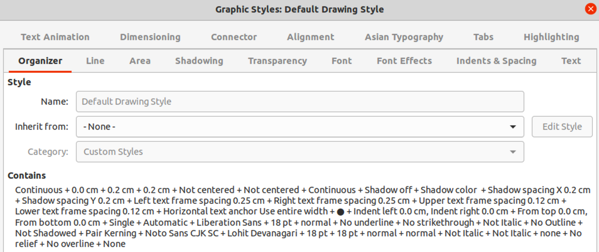
2) Right click on the style required as a starting point to create a custom style and select New from the context menu to open the Graphic Styles dialog (Figure 30).
3) Click on the Organizer tab to open the Organizer page in the Graphic Styles dialog.
4) In the Name text box, enter a unique style name.
5) In Inherit from text box, select None from the drop-down list if the new drawing style is NOT going to be linked. When the object was created, it was allocated the Default Drawing Style and this new drawing style is linked by default to the Default Drawing Style.
6) If the new style is to inherit settings from an existing style, select a style from the Inherit from: drop-down list.
7) Use the options on the various pages of the Graphic Styles dialog to format and categorize a new style.
Organizer – contains a summary of the style and its hierarchical position.
Font, Font Effects, Indents & Spacing, Alignment, and Tabs – sets the attributes of the text inserted into a text box or graphic object.
Dimensioning – sets the style of dimension lines when used on an object.
Text, Text Animation, Connector, Line, Area, Shadowing, Highlighting and Transparency – sets the attributes for the object format..
8) Click OK when finished to save the new style and close the Graphic Styles dialog.
Note
Any new drawing style created is automatically placed in the Custom Styles category.
Using New Style from Selection allows all formatting to be made to an object first and then create a drawing style from that object.
1) Select an object to create a new style from, or create a new object in a drawing.
2) Format the object using the tools and options from the Graphic Styles dialog, Area dialog, Line dialog, Properties deck on the Sidebar, or Line and Filling toolbar.
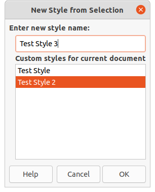
Figure 31: New style from Selection dialog
3) Create the new style using one of the following methods:
Open the Styles deck on the Sidebar and click on New Style from Selection at the top right of the deck.
Go to Format > Styles > New Style from Selection on the Menu bar.
4) In the New Style from Selection dialog (Figure 31), type a unique name for the new style. This dialog also shows existing custom styles.
5) Click OK to save the new style and close the New Style from Selection dialog.
It is recommended to only modify custom styles that have been created. Modifying styles that are installed with LibreOffice may cause problems in other documents that use one of these styles.
1) Select an object in a drawing.
2) Click on Styles on the left of the Sidebar to open the Styles deck.
3) Open the Graphic Styles dialog using one of the following methods:
Go to Format > Styles > Edit Style on the Menu bar.
Right-click on the object and select Edit Style from the context menu.
Right-click on the style that is highlighted in the Styles deck on the Sidebar and select Modify from the context menu.
4) Use the options on the various pages of the Graphic Styles dialog to modify the style.
5) Click OK to save the changes and close the Graphic Styles dialog.
If an object in a drawing uses a style that is linked to a hierarchical or parent style, then it is possible to edit the hierarchical or parent style.
1) Select an object in a drawing that uses a linked style.
2) Open the Graphic Styles dialog and click on Organizer to open the Organizer page in the Graphic Styles dialog.
3) Check that the style name in the Inherit from text box is the hierarchical or parent style for editing, then use the options on the various pages in the Graphic Styles dialog to edit the style.
4) If the hierarchical or parent style is NOT the one required:
a) Click on Edit Style to the right of the Inherit from text box until the name of the style is displayed.
b) Use the options on the various pages in the Graphic Styles dialog to edit the style.
5) Click OK to save the changes and close the Graphic Styles dialog.
Note
It is recommended to create custom hierarchical styles rather than modify the existing hierarchical styles available in LibreOffice. Modifying hierarchical styles installed with LibreOffice may cause problems if the style has been used in other drawings.
Using Update Style allows all the formatting to an object to be made first and then update the drawing style used by the object.
1) Select the object to modify the drawing style the object uses.
2) Format the object using the tools and options from the Graphic Styles dialog, Area dialog, Line dialog, Properties deck on the Sidebar, or Line and Filling toolbar.
3) Update the drawing style using one of the following methods. There is no confirmation when updating a drawing style.
Open the Styles deck on the Sidebar and click on Update Style at the top right.
Go to Format > Styles > Update Selected Style on the Menu bar
Note
Make sure to only update custom styles that have been created. Updating styles that are part of the default installation of LibreOffice could cause problems in other documents that use LibreOffice drawing styles.
Drawing styles are applied to an object using the Styles deck on the Sidebar as follows:
1) Select the object to apply a drawing style.
2) Click on Styles on the Line and Filling toolbar, or click on Styles on the Sidebar.
3) Double click on the style name to apply the drawing style to the selected object.
Predefined styles in LibreOffice cannot be deleted, even if they are not being used. Only custom styles can be deleted. However, before deleting a custom style, it is recommended to make sure the drawing style is not in use by checking the list of drawing styles in the Applied Styles category.
1) To open a list of styles, use one of the following methods:
Click on Styles on the Line and Filling toolbar.
Click on Styles on the Sidebar.
2) Select Applied Styles from the drop-down list at the bottom of the Styles deck on the Sidebar.
3) Right click on the style name in the styles list and select Delete from the context menu.
4) If the style is used on an object, a warning message will appear stating that the selected object will revert back to the default drawing style. Select Yes to confirm deletion of the style.
5) If the style is not in use, select Yes to confirm deletion of the style and there is no confirmation message.
As well as the basic actions of moving and resizing an object, a number of special effects can also be applied to objects in Draw. Several of these effects are readily available in the Transformations toolbar. If the Transformations toolbar (Figure 20 on page 1) is not showing, select it from View > Toolbars > Transformations on the Menu bar.
The tools on the Transformations toolbar are described in the following sections with the exception of the In 3-D Rotation Object tool, which is described in Chapter 7, Working with 3D Objects.
1) Select the object for rotation so that the selection handles are displayed.
2) Use one of the following methods to switch the selected object into rotation mode,. The selection handles change shape and color when in rotation mode (Figure 32).
Click again on the selected object.
Click on the triangle ▼ to the right of Transformations on the Line and Filling and select Rotate from the context menu.
If the Transformations toolbar is displayed, click on Rotate.
3) Move the cursor over one of the corner handles and the cursor changes shape.
4) Click, hold and drag the object in the rotation direction. Only the corner selection handles are active for rotation.
5) To restrict the rotation angles to multiples of 15 degrees, press and hold the Shift key while rotating the object. This is very handy for rotating objects through 90 deg, for example from portrait to landscape.
6) When satisfied with the rotation, release the cursor.
Figure 32: Manually rotating objects
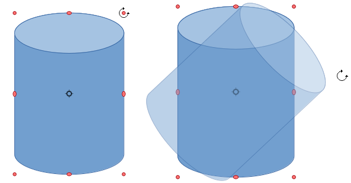
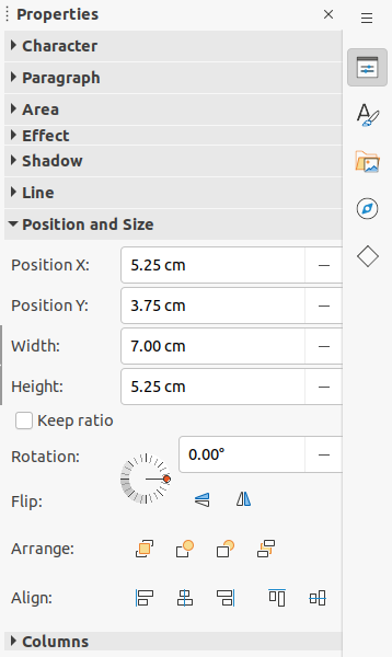
Figure 33: Position and Size panel in Properties deck on Sidebar
7) By default, the rotation pivot point is a small circle in the center of the selected object. To change the center of object rotation, click, hold and drag the rotation pivot point to a new position. This position for the rotation pivot point can be outside of the selected object.
1) Select the object for rotation so that the selection handles are displayed.
2) Open the Position and Size panel in the Properties deck on the Sidebar (Figure 33).
3) Rotate the object using one of the following options:
4) When satisfied, click outside the object to deselect the object and deselect rotation mode.
1) Select the object for rotation so that the selection handles are displayed.
2) Open the Position and Size dialog (Figure 34) using one of the following methods:
Use the keyboard shortcut F4.
Select Format > Position and Size on the Menu bar.
Right-click on the object and select Position and Size from the context menu.
3) Click Rotation to open the Rotation page.
4) If required, in Pivot Point enter a value for Position X and Position Y to move the position of the pivot point. The default position of the pivot point is the center of the object. Alternatively, select a pivot point from one of the 9 positions in Default settings.
5) In Rotation Angle, rotate the object using one of the following methods:
In the Angle text box, enter the degrees of rotation required.
Click on and drag the rotation indicator in Default settings.
6) Click OK to save the changes and close the Position and Size dialog.
1) Select the object for flipping so that the selection handles are displayed.
2) Use one of the following methods to flip the object vertically or horizontally:
Right click on the object and select Flip > Horizontally or Flip > Vertically from the context menu.
Figure 34: Position and Size dialog - Rotation page
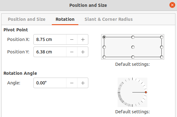
Figure 35: Example of using Flip tool
In the Position and Size section of the Properties deck on the Sidebar, click on Flip Vertically or Flip Horizontally.
In the Line and Filling toolbar, click on Vertically or Horizontally.
Go to Shape > Flip > Vertically or Horizontally on the Menu bar.
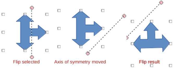
Using the Flip tool on the Transformations toolbar (Figure 20 on page 1), the position and angle that the object flips over can be changed, as shown in Figure 35.
1) Select the object for flipping so that the selection handles are displayed.
2) Click on Flip on the Transformations toolbar and the symmetry axis appears as a dashed line through the middle of the object. The object will be flipped about this symmetry axis.
3) Click and drag one or both ends of the symmetry axis to set the orientation of the axis.
4) Place the cursor over one of the object selection handles until it changes shape.
5) Click, hold and drag the object across to the other side of the symmetry axis until the object appears flipped over. The angle and position of the flip depends on the angle and position of the symmetry axis.
6) Release the click and the object is flipped.
Note
Pressing and holding the Shift key while moving the symmetry axis allows rotation in 45 degree increments.
At the moment there is no mirror command existing in Draw. However, mirroring an object can be emulated by copying and flipping the object as follows:
1) Select the object to make a mirror copy of and copy the object to the clipboard.
2) Flip the object using the procedures in “Flipping objects” above.
3) Click in an empty area on the drawing to deselect the object.
4) Paste the copy of the original object back into its original location, creating a mirror copy.
5) If necessary, select both objects and align them using one of the following methods:
Go to Shape > Align on the Menu bar and use one of the alignment options.
Right-click the selected objects and select Align from the context menu, then select one of the alignment options.
Three tools on the Transformations toolbar allow an object to be distorted.
Distort – distorts an object in perspective.
Set to circle (slant) and Set in Circle (perspective) – both create a pseudo 3D effect.
Before distorting an object, the object must be converted to a curve. Click, hold and drag on one of the selection handles produces the desired effect. Examples of distortion are shown in the following figures.
Note
Transforming an object into a curve is a safe operation, but cannot be reversed other than by clicking Format > Undo on the Menu bar.
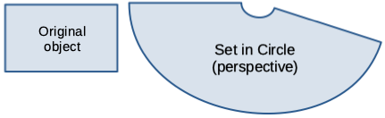
An example of distorting an object with the Set in Circle (perspective) tool is shown in Figure 36.
1) Select an object and click on the Set in Circle (perspective) in the Transformations toolbar.
2) Click Yes to convert the object to a curve. If the object is already a curve, this dialog does not appear.
3) Click and drag one of the selection handles to give a pseudo 3D perspective using the opposite side as an anchor point. A ghosted image appears as the object is distorted to give an indication of how the resulting object will look.
Figure 36: Example of using Set in Circle (perspective) distortion
An example of distorting an object with the Set to circle (slant) tool is shown in Figure 37.
1) Select an object and click on the Set to circle (slant) in the Transformations toolbar.
2) Click Yes to convert the object to a curve. If the object is already a curve, this dialog does not appear.
3) Click and drag one of the selection handles to give a pseudo 3D perspective using the opposite side as an anchor point. A ghosted image appears as the object is distorted to give an indication of how the resulting object will look.
Figure 37: Example of using Set to Circle (slant) distortion
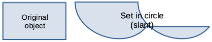
Figure 38: Examples of object distortion
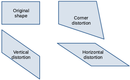
Examples of distorting an object with the Distort tool are shown in Figure 38.
1) Select an object and click on Distort on the Transformations toolbar.
2) Click Yes to convert the object to a curve. If the object is already a curve, this dialog does not appear.
3) Click, hold and drag a corner selection handle to distort the object using the opposite corner selection handle as an anchor point for the distortion.
4) Click and drag the vertical selection handles to distort the object using the opposite vertical side as an anchor point for the distortion.
5) Click, hold and drag the horizontal selection handles to distort the object using the opposite horizontal side as an anchor point for the distortion.
Transparency gradients are controlled in the same manner as color gradients and both types of gradient can be used together. With a transparency gradient, the direction and degree of object fill color changes from opaque to transparent. In a color gradient, the fill changes from one color to another, but the degree of transparency remains the same.
Two icons on the Transformations toolbar dynamically control transparency and color gradients. Even if an object with a color fill is not assigned transparency, the transparency can be controlled by clicking on Interactive transparency tool. This defines a transparency gradient and a dashed line connecting two squares appears on the object. Move the two squares to modify the gradient. Define the direction of the gradient (vertical, horizontal, or at any angle) and the spot at which the transparency begins.
A regular color gradient is defined in the same manner. Select an object, then select a gradient area fill (see “Gradient fills” on page 1 for more information). The Interactive gradient tool is now active on the Transformations toolbar. When clicking on Interactive gradient tool, a dashed line connecting two squares appears on the object, just as it does for a transparency gradient.
In both transparency gradient and gradient fill, click outside the object to set the gradient.
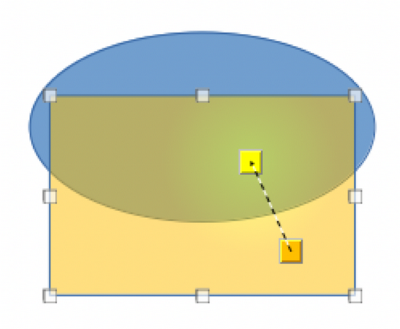
In the example shown in Figure 39 there is a single color object and a transparency gradient, covering part of the underlying object. This gradient transparency can be dynamically adjusted. Direction of transparency is changed by moving the white square and the distance over which it is applied by moving the green square.
Figure 39: Example of dynamic gradient
Note
Moving the squares has different effects, depending on the type of gradient. For example, for a linear gradient, the start and end squares of the gradient will always be situated to either side of the center point of the object.