
Draw Guide 7.3
Chapter 7,
Working with 3D Objects
This document is Copyright © 2022 by the LibreOffice Documentation Team. Contributors are listed below. You may distribute it and/or modify it under the terms of either the GNU General Public License (https://www.gnu.org/licenses/gpl.html), version 3 or later, or the Creative Commons Attribution License (https://creativecommons.org/licenses/by/4.0/), version 4.0 or later.
All trademarks within this guide belong to their legitimate owners.
|
Peter Schofield |
Regina Henschel |
|
|
John Cleland |
Martin Fox |
Jean Hollis Weber |
|
John A Smith |
Peter Schofield |
Regina Henschel |
|
Claire Wood |
Elzett Kotze |
|
Please direct any comments or suggestions about this document to the Documentation Team’s mailing list: documentation@global.libreoffice.org
Note
Everything sent to a mailing list, including email addresses and any other personal information that is written in the message, is publicly archived and cannot be deleted.
Published May 2022. Based on LibreOffice 7.3 Community.
Other versions of LibreOffice may differ in appearance and functionality.
Some keystrokes and menu items are different on macOS from those used in Windows and Linux. The table below gives some common substitutions for the instructions in this document. For a detailed list, see the application Help.
|
Windows or Linux |
macOS equivalent |
Effect |
|
Tools > Options on Menu bar |
LibreOffice > Preferences on Menu bar |
Access to setup options |
|
Right-click |
Ctrl+click and/or right-click depending on computer setup |
Opens a context menu |
|
Ctrl or Control |
⌘ and/or Cmd or Command |
|
|
Alt |
⌥ and/or Alt or Option |
Used with other keys |
|
F11 |
⌘+T |
Open the Styles deck in the Sidebar |
Although Draw does not match the functionality of leading drawing or image editing programs, it is capable of producing and editing 3D drawings. In Draw, two types of 3D objects are available: 3D scenes and extruded 3D shapes. The Status Bar indicates when a 3D scene has been selected (Figure 1), but only indicates a shape has been selected (Figure 2) when an extruded 3D shape is selected.
Depending on which type is selected, there are different possibilities for further editing of the object (rotation, illumination, perspective, and so on). Extruded 3D shapes are simpler to set up and edit, but 3D scenes allow for greater customization.
3D objects are created using one of the following methods:
3D Objects – these are ready made 3D objects and are also 3D scenes. They are selected using one of the following methods:
Click on 3D Objects in the Drawing toolbar (Figure 3).
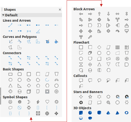
Select a 3D object in the 3D Objects panel in the Shapes deck on the Sidebar (Figure 4).
Convert a 2D object into a 3D object use one of the following tools. These tools are either available on the Drawing toolbar, by right-clicking on the object and selecting from the context menu, or the 3D Effects dialog:
To 3D – creates a 3D scene containing an extrusion object.
To 3D Rotation Object – creates a 3D scene using a default rotation axis.
Toggle Extrusion – creates a 3D shape by extruding a 2D object into 3D. Only 3D shapes that have been extruded can be converted back to a 2D object.
Convert To Rotation Object – available in the 3D Effects dialog. Converts a selected 2D object into a 3D rotation object. Also, selecting several ungrouped 2D objects can be converted into a single 3D rotation object.
Note
Before creating 3D objects in a drawing, it is recommended that the extra 3D tools (To 3D; To 3D Rotation Object; Toggle Extrusion) are added to the Drawing toolbar (Figure 3) using Visible Buttons or the Customize dialog. For more information on using Visible Buttons and the Customize dialog, see Appendix B, Toolbars and the Getting Started Guide.
After installing these extra 3D tools onto the Drawing toolbar, they only become available for use when a 2D object is selected in a drawing.
Figure 1: Status Bar showing 3D scene selected

Figure 2: Status Bar showing shape selected

Figure 3: Drawing toolbar with 3D tools highlighted
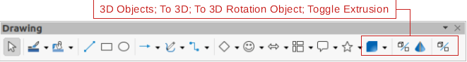
Figure 4: Shapes deck on Sidebar
3D scenes are created from objects with dimensions using x, y, and z coordinates and can contain object types, such as cube, sphere, extrusion object or rotation object. These object types do not exist outside a 3D scene.
The Status Bar displays 3D scene selected when a 3D object is selected that has been created from a 2D object using body rotation or conversion, or it is a ready-made 3D object that has been inserted into a drawing.
A 3D scene is similar to a group. Just like a group, a 3D scene can be entered for editing an individual object in the 3D scene and then exit after editing is completed. See Chapter 5, Combining Multiple Objects for more information on entering, editing and exiting groups.
When a 3D scene is created from a selection of more than one 2D object, a group is automatically created as a single 3D scene. This 3D scene can be entered so that individual objects within the 3D scene can be changed, edited and rotated.
Note
Individual objects cannot be ungrouped when a 3D scene has been created from a selection of 2D objects.
2D shapes are flat with only width and height dimensions, but 3D shapes are solid objects that have three dimensions: depth, width, and height.
A 3D shape is created when a 2D shape or an object from the Fontwork Gallery is turned into 3D using Toggle Extrusion. The Status Bar displays Shape selected when this type of 3D object is selected.
A 3D shape can be viewed and edited in 3D or 2D mode. To edit in 2D mode, switch off extrusion, make the editing changes, and switch back to 3D mode using Toggle Extrusion.
Note
Toggle Extrusion can only be used when a 2D shape, a 3D object that has been extruded from a 2D shape, or an object from the Fontwork Gallery is selected in a drawing. It is not available for text, lines, arrows, curves, and polygons.
3D ready made objects are 3D scenes and are inserted into a drawing using one of the following methods. The selection and drawing of 3D objects is the same for all methods of inserting a 3D ready made object.
Click on the triangle ▼ to the right of 3D Objects on the Drawing toolbar and select a 3D object from the sub-toolbar. The 3D Objects icon displayed on the Drawing toolbar depends on the 3D object that had been previously selected and used.
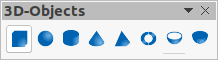
Go to View > Toolbars > 3D-Objects on the Menu bar to open the 3D-Objects toolbar (Figure 5).
Go to Shapes > Insert > 3D Objects on the Menu bar and select a 3D object from the submenu.
Go to the 3D Objects panel in the Shapes deck on the Sidebar and select a 3D object.
Figure 5: 3D-Objects toolbar
Note
Ready made 3D objects can be repositioned, resized, and edited in the same way as 2D objects. See Chapter 3, Working with Objects for more information.
Extrusion converts a 2D object into a 3D scene by extruding the 2D object toward the observer. The scene is rotated by 20 degrees around the horizontal axis to make the 3D effect more visible. Examples of 3D conversion using extrusion are shown in Figure 6. After selecting a 2D object, convert it to a 3D scene using one of the following methods:
Right-click on the 2D object and select Convert > To 3D from the context menu.
Click on To 3D in the Drawing toolbar.
Figure 6: Example of using extrusion for 3D conversion
Go to Shape > Convert > To 3D on the Menu bar.
Click on Convert to 3D in the 3D Effects dialog. For more information see “3D effects” on page 1.
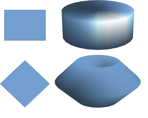
To 3D Rotation Object or Convert to Rotation Object converts a 2D object into a 3D scene by rotating the object using the left edge of the bounding box around the object as the axis of rotation. Examples of 3D conversion using either of these rotation tools are shown in Figure 7. The actual 3D scene created depends on the angle and shape of the object being rotated.
After selecting a 2D object in a drawing, convert it to a 3D scene using rotation with one of the following methods:
Right-click on a 2D object and select Convert > To 3D Rotation Object from the context menu.
Click on To 3D Rotation Object in the Drawing toolbar.
Go to Shape > Convert > To 3D Rotation Object on the Menu bar.
Click on Convert To Rotation Object in the 3D Effects dialog. For more information see “3D effects” on page 1.
Figure 7: Examples of using rotation for 3D conversion
Extrusion is where parallel surfaces are moved to create a 3D shape. In Draw, the 2D surface is moved forwards out of the drawing level. At the same time the object is slightly tilted and central projection turned on, creating the impression of a 3D shape. Draw uses a default value for this extrusion (body depth) based on the size of the 2D object. The value can be changed after the extrusion, see “Editing 3D objects” below.
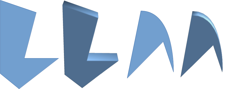
Figure 8: Examples of toggle extrusion
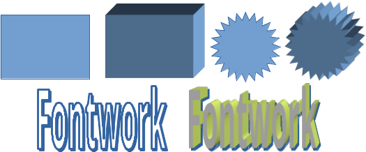
Extrusion conversion is carried out using Toggle Extrusion. Extrusion only works on Basic Shapes, Symbol Shapes, Block Arrows, Flowcharts, Callouts, Stars and Banners, and Fontwork that are included as a part of the default set of tools on the Drawing toolbar or in the Shapes deck on the Sidebar. Examples of toggle extrusion are shown in Figure 8.
1) Select a 2D object in a drawing that has been created from Basic Shapes, Symbol Shapes, Block Arrows, Flowcharts, Callouts, Stars and Banners, or Fontwork.
2) Click on Toggle Extrusion on the Standard or Drawing toolbar to convert the 2D object into a 3D shape.
3) To convert a 3D conversion back into a 2D object, select the 3D object and click on Toggle Extrusion on the Standard or Drawing toolbar.
Note
Extrusion cannot be used on text objects created using Insert Text Box or Insert Vertical Text.
Note
Where 3D scenes have been created from more than one 2D object, a 3D scene group is automatically created. This 3D scene group cannot be ungrouped and any editing carried out will affect all 3D objects within the group. To edit an individual 3D object within this 3D scene group, enter the group. For more information on working with groups, see Chapter 5, Combining Multiple Objects.
Editing the position, size and rotation of 3D objects is similar to 2D objects. See Chapter 3, Working with Objects for more information.
To open the 3D‑Settings toolbar (Figure 9), go to View > Toolbars > 3D‑Settings on the Menu bar. The 3D‑Settings toolbar only becomes active when a 3D shape is selected that has been created from a 2D object using “Toggle Extrusion” above.
The tools available for editing 3D shapes are as follows. The result of any changes made using these editing tools is applied to the selected 3D shape immediately displaying the effect of the 3D setting applied. Figure 10 shows an example of tilting left, increasing extrusion depth, and changing 3D color using the 3D‑Settings toolbar.
Figure 9: 3D Settings toolbar
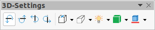
Figure 10: Example of changing 3D settings

Tilt Down – tilts the selected object downward (horizontal axis rotation) by 5 degrees each time the icon is used.
Tilt Up – tilts the selected object upward (horizontal axis rotation) by 5 degrees each time the icon is used.
Tilt Left – tilts the selected object left (vertical axis rotation) by 5 degrees each time the icon is used.
Tilt Right – tilts the selected object right (vertical axis rotation) by 5 degrees each time the icon is used.
Depth – opens a pop-up menu where the extrusion depth can be set from an object by a fixed or custom amount.
Direction – opens a pop-up menu where the view direction can be set to create an extrusion in either a perspective or parallel projection.
Lighting – opens a pop-up menu where the direction and intensity of the lighting can be set when creating an extrusion.
Surface – opens a pop-up menu where the surfaces of the object can be set as Wire Frame, Matt, Plastic, or Metal display.
3D Color – opens a pop-up menu where the color used for the extrusion can be set. This color does not have to be the same as the color used for the original 2D object.
The 3D Effects dialog (Figure 11) offers a wide range of possible settings for editing 3D ready made objects or 3D scenes. This dialog can also be used to convert a 2D object to 3D using the tools in the bottom left corner of the dialog. To open the 3D Effects dialog, use one of the following methods:
Click on 3D Effects on the Standard toolbar.
Click on 3D Effects on the Line and Filling toolbar.
Go to Format > 3D-Effects on the Menu bar.
Any 3D effects applied to a 3D scene are not carried out until Assign is clicked in the top right of the 3D Effects dialog. This allows for all 3D effect changes to be carried out before applying them to a 3D scene.
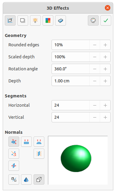
Figure 11: 3D Effects dialog - Geometry page
Note
The 3D Effects dialog cannot be used on 3D shapes created using Toggle Extrusion because the correct formatting results will not be achieved. If the 3D Effects dialog is used in error, remove any incorrect formatting by going to Format > Default Formatting on the Menu bar.
Note
Any options on the pages in the 3D Effects dialog that are grayed out cannot be used for the selected object.
In the bottom left corner of the 3D Effects dialog are tools for converting a 2D object into a 3D scene and changing the projection used in a 3D scene.
Convert to 3D – converts the selected object into a 3D scene. This tool works in the same way as using “Extrusion” on page 1.
Convert to Rotation Object – converts a 2D object into a 3D scene using body rotation. This tool works in the same way as using “Rotation” on page 1.
Perspective On/Off – switches perspective projection on or off for a 3D scene. Perspective projection is a technique to create a linear illusion of depth. As objects get further away from the viewer, a perspective drawing decreases in size at a constant rate.
Note
The 3D Effects dialog has five pages to provide options for Geometry, Shading, Illumination, Textures, and Material. The tools to change pages for the different types of 3D effects are located at the top left of the 3D Effects dialog.
Click on Geometry in the 3D Effects dialog (Figure 11) to open the Geometry page and use the options available to change the geometry of a 3D object.
Geometry – defines the properties of an object in a 3D scene.
Rounded edges – enter the amount required to round the corners of a 3D shape as shown by the example in Figure 12. The default setting for rounded edges is 10%.
Scaled depth – enter the amount required to increase or decrease the frontal area of a selected 3D object. Figure 13 shows an example where the scaled depth has been increased to 150% and then decreased to 50%. The default setting for scaled depth is 100%.
Rotation angle – enter the angle in degrees to rotate a 2D object that has been converted to 3D using To 3D Rotation Object. Figure 14 shows an example of a 2D circle where the rotation angle is changed to 150 degrees.
Depth – enter the extrusion depth for the selected 2D object that has been converted to 3D using To 3D. Figure 15 shows an example of a 2D circle converted to a 3D cylinder with the extrusion depth increased to 3 cm.
Figure 12: Example of rounded edges
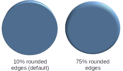
Figure 13: Example of changing scaled depth
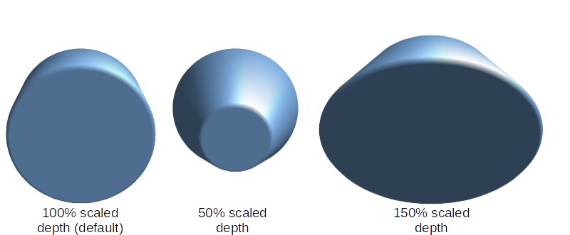
Figure 14: Example of changing rotation angle
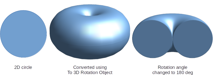
Figure 15: Example of increasing depth
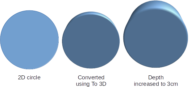
Figure 16: Example of segments
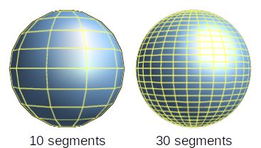
Segments – changes the number of segments that Draw uses to draw a 3D rotation object. The higher the number of segments, the smoother the object surface will be. However, a high segment number may increase the time it takes to generate the 3D object on a display. Figure 16 shows the difference on a 3D sphere when the segments have been increased from 10 to 30 segments horizontally and vertically.
Horizontal – enter the number of horizontal segments used in the selected 3D rotation object.
Vertical – enter the number of vertical segments used in the selected 3D rotation object.
Object-Specific – renders the 3D surface according to the shape of the object. For example, a circular shape is rendered with a spherical surface.
Flat – renders the 3D surface as polygons.
Spherical – renders a smooth 3D surface regardless of the shape of the object.
Figure 17: Examples of object specific, flat and spherical effects
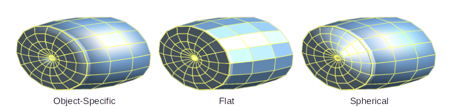
Figure 18: Examples of invert normals and double sided illumination
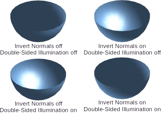
Invert Normals – an inverted normal is a normal that is pointing in the wrong direction. This tells a computer that an outside face is actually an inside face when it is not. If there is a hollow design, an inverted normal can be indicated because both surfaces facing are in and out in the same model.
Double-Sided Illumination – lights the outside and the inside of the object. This has only an effect, if the inside is drawn at all, see Double-Sided. This is a setting for the whole of the 3D scene and not for a single object within the scene.
Note
Figure 18 demonstrates the 3D effect of using Invert Normals in conjunction with using the 3D effect Double-Sided Illumination.
Double-Sided – a 3D object has outside (front) and inside (back) faces. With Double-Sided switched off, only the outside face of the object is rendered. The effect, when looking from outside, is that the object is solid, but, when looking from inside, the front face is transparent. If there is no view to the inside face, normal for an extruded 3D object with solid texture, Double-Sided should be switched off to improve performance during rendering. Any 3D object created using rotation often allows an inside view and it is recommended that Double-Sided is switched on.
On the Shading page of the 3D Effects dialog (Figure 19) provides options to set the shading, shadow, and camera effects on a selected 3D object.
Figure 19: 3D Effects dialog - Shading page
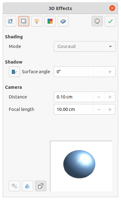
Figure 20: Examples of shading mode
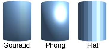
Shading – specifies the mode of shading applied to a 3D object (Figure 20).
Gouraud – this shading mode is a method used in computer graphics to simulate the differing effects of light and color across the surface of an object. In practice, it is used to achieve smooth lighting on low-polygon surfaces without the heavy computational requirements of calculating lighting for each pixel.
Phong – this shading mode is an interpolation technique for surface shading calculating the normal of a point in the polygon by interpolating the normals of the vertices. The angle between normal and lighting direction determines how much of the lighting is used to color the pixel.
Flat – this shading mode refers to the depiction of depth perception in 3D models or illustrations by varying the level of darkness. It assigns a single color of shading to a single segment on the surface of the object.
Figure 21: Examples of shadow surface angle
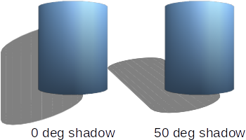
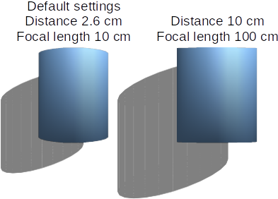
Figure 22: Example of changing camera settings
Shadow – adds or removes a shadow from a selected 3D object (Figure 21). A shadow is generated only from the first light source. Enter a Surface Angle from the light source to the surface between 0 to 90 degrees to cast a shadow.
Camera – sets the camera options for a selected 3D scene as if a camera is being used to take a photograph (Figure 22). The settings affect only central perspective and not parallel projection.
Distance – enter the distance to leave between the camera and the center of the selected 3D scene. The default setting for distance is 2.6cm.
Focal length – enter the focal length of the camera lens, where a small value corresponds to a fish-eye lens and a large value to a telephoto lens. The default setting for focal length is 10cm.
The Illumination page of the 3D Effects dialog (Figure 23) defines how a 3D scene is lit and the settings apply to all 3D objects in a scene. The direction of the light source, color of the light source, and the ambient light can be specified for the 3D scene.
By default, one light source is already selected when the Illumination page is opened. More light sources can be selected for illumination. A maximum of eight sources can be used and each light source can use a different color. Figure 23 shows three light sources selected with each light source having a different color.
1) Select a Light source to turn the light source on. The icon changes to an illuminated bulb.
2) Click again on the selected light source to adjust the color for the light source.
3) Select a color for the light from one of the color palettes in the Light source drop-down list. A different color can be used for each light source selected.
Figure 23: 3D Effects dialog - Illumination page
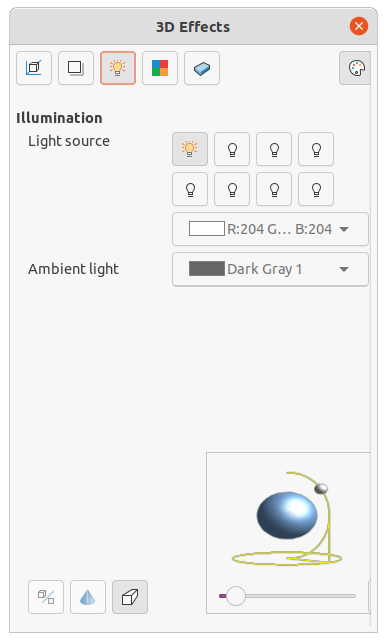
4) Select a color from one of the color palettes in the Ambient light drop-down list to set the color of the surrounding light.
5) To deselect a light source, select a light source already selected and click on it again.
The light source location and color are shown in the lower right corner of the Illumination page. The vertical slider bar adjusts the lighting angle and the horizontal slider bar rotates the light about the object. Alternatively, click on the light point and drag the light source to the required position.
To change the preview from a sphere to a cube, click on the small square to the right of the horizontal slider bar and below the vertical slider bar.
Each light source selected is shown as a small colored sphere in the color specified for it. The larger colored sphere indicates the active light source.
On the Textures page of the 3D Effects dialog (Figure 24) the properties of the surface texture can be set for a selected 3D object. Textures is only available after the area fill of a 3D object is set to Gradient, Image, Pattern, or Hatch. For more information on changing area fill, see Chapter 4, Changing Object Attributes.
Figure 24: 3D Effects dialog- Textures page
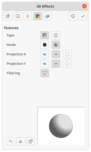
Type – sets the color properties of the texture.
Black & White – converts the texture to black and white.
Color – converts the texture to color.
Mode – shows or hides shading.
Only Texture – applies the texture without shading.
Texture and Shading – applies the texture with shading to lighten or darken the illumination.
Projection X – sets the options for displaying the texture along the X axis. Only one of the three following options can be selected.
Object-Specific – automatically adjusts the texture for best fit based on the shape and size of the object. This is the default setting except for extrusion objects.
Parallel – applies the texture parallel to the horizontal axis and is mirrored on the rear side of the object. This is the default setting for extrusion objects.
Circular – wraps the horizontal axis of the texture pattern around an object.
Projection Y – sets the options for displaying the texture along the Y axis. Only one of the three following options can be selected.
Object-Specific – automatically adjusts the texture for best fit based on the shape and size of the object. This is the default setting except for extrusion objects.
Parallel – applies the texture parallel to the vertical axis and is mirrored on the rear side of the object. This is the default setting for extrusion objects.
Circular – wraps the vertical axis of the texture pattern around an object.
Filtering – filters out noise that can occur when a texture is applied to a 3D object.
Filtering On/Off – applies a soft focus filter blurring the texture slightly to remove unwanted speckles.
On the Materials page of the 3D Effects dialog (Figure 25) the appearance of a 3D object can be changed to represent different materials. Materials and textures can be combined with each other and it is a matter of trial and error to achieve the desired result.
Material – assigns a color from a color palette. For custom colors, see Chapter 11, Advanced Draw Techniques for more information on creating custom colors.
Favorites – select a material type for the selected object from the Favorites drop-down list.
Object color – select a color from one of the color palettes in the Object color drop‑down list to apply to the object.
Illumination color – select a color from one of the color palettes in the Illumination color drop-down list. This illuminates the object and brightens parts of the object which lie in shadow making the object seem more illuminated.
Figure 25: 3D Effects dialog - Material page
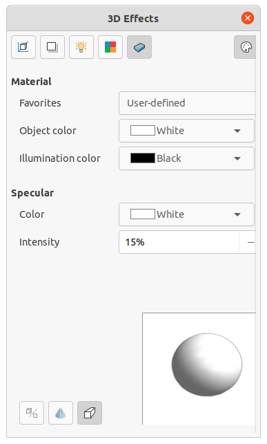
Specular – sets the light reflection properties for the selected object simulating the reflecting capacity of the surface. The position of the illuminated point is determined by the setting of the first light source.
Color – select a color to be reflected from the object from one of the color palettes in the Color drop-down list.
Intensity – enter the intensity of the specular effect as a percentage.
Colors Dialog – opens the Pick a Color dialog where custom colors are defined using the two-dimensional graphic and numerical gradient chart. Any colors created are stored in the custom palette. See Chapter 11, Advanced Draw Techniques for more information on creating custom colors.
Note
Metallic and glass surfaces do not simulate well because the appearance of these materials is produced using reflection.
Tip
Do not use a very high brightness value for individual colors. Colors are additive and it is easy to end up with a colored area that is white.
Multiple 3D objects cannot be combined using Shape > Combine on the Menu bar or the keyboard shortcut Ctrl+Shift+K (macOS ⌘+Shift+K). Multiple 2D objects have to be created first, then a single 3D object created as follows (see Chapter 5, Combining Multiple Objects for more information on combining objects):
1) Create multiple 2D objects and carry out all the necessary editing changes.
2) Make sure that all 2D objects are selected to create a single 3D object.
3) Create a single 3D object combining the multiple 2D objects using one of the following methods (example conversions are shown in Figure 26):
Click on To 3D or To 3D Rotation Object on the Drawing toolbar.
Right-click on the selected multiple 2D objects and select Convert > To 3D or To 3D Rotation Object from the context menu.
Go to Shape > Convert > To 3D or To 3D Rotation Object on the Menu bar.
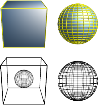
3D objects that each form a separate 3D scene can be combined or assembled into a single 3D scene. An example procedure for assembling 3D objects is as follows and shown in Figure 27:
1) Select a 3D object (for example, a cube) from 3D Objects on the Drawing toolbar or Shapes deck on the Sidebar and place it in a drawing.
2) Select a second 3D object (for example, a sphere) from 3D Objects on the Drawing toolbar or Shapes deck on the Sidebar and place it in the drawing.
3) If necessary, set the area fill to None and the lines to Continuous to create wire frame objects. This makes it easier to position both objects in the assembled 3D scene.
4) Select the second 3D object (sphere) and go to Edit > Cut on the Menu bar or right-click on the object and select Cut from the context menu.
Figure 26: Example of creating single 3D object from multiple 2D objects
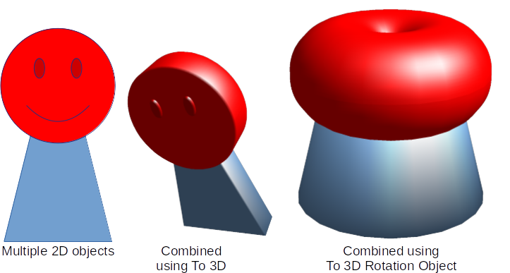
Figure 27: Example of assembling 3D objects
5) Double-click the first 3D object (cube) to enter the group or go Shape > Group > Enter Group on the Menu bar.
6) Go to Edit > Paste on the Menu bar or right-click on the first 3D object and select Paste from the context menu. The sphere now appears inside the cube and is now part of the same group.
7) If required, edit the individual objects or change their position within the group.
8) Double-click outside the 3D assembled scene to exit the group, or go to Shape > Group > Exit Group on the Menu bar.
Note
The second object also reappears in its original position when Paste is carried out. This object is NOT part of the assembled 3D scene and can be deleted if necessary.