
Draw Guide 7.3
Chapter 11,
Advanced Draw Techniques
This document is Copyright © 2022 by the LibreOffice Documentation Team. Contributors are listed below. This document maybe distributed and/or modify it under the terms of either the GNU General Public License (https://www.gnu.org/licenses/gpl.html), version 3 or later, or the Creative Commons Attribution License (https://creativecommons.org/licenses/by/4.0/), version 4.0 or later.
All trademarks within this guide belong to their legitimate owners.
|
Peter Schofield |
Kees Kriek |
|
|
Martin Fox |
John Cleland |
Jean Hollis Weber |
|
John A Smith |
Peter Schofield |
Regina Henschel |
Please direct any comments or suggestions about this document to the Documentation Team’s mailing list: documentation@global.libreoffice.org
Note
Everything sent to a mailing list, including email addresses and any other personal information that is written in the message, is publicly archived and cannot be deleted.
Published May 2022. Based on LibreOffice 7.3 Community.
Other versions of LibreOffice may differ in appearance and functionality.
Some keystrokes and menu items are different on macOS from those used in Windows and Linux. The table below gives some common substitutions for the instructions in this document. For a detailed list, see the application Help.
|
Windows or Linux |
macOS equivalent |
Effect |
|
Tools > Options on Menu bar |
LibreOffice > Preferences on Menu bar |
Access to setup options |
|
Right-click |
Ctrl+click and/or right-click |
Opens a context menu |
|
Ctrl or Control |
⌘ and/or Cmd or Command |
|
|
Alt |
⌥ and/or Alt or Option |
Used with other keys |
|
F11 |
⌘+T |
Open the Styles deck in the Sidebar |
A drawing created in Draw can consist of multiple pages allowing a drawing to be stored as one file on a computer. The drawing pages are displayed as thumbnails in the Pages page which is used to add, rename, delete, and arrange pages in a drawing.
By default the Pages page (Figure 1) appears docked on the left of the Workspace. If the Pages pane is not visible, go to View > Page Pane on the Menu bar. The Pages pane can also become a floating window using one of the following methods:
For Windows and Linux only –– press and hold the Ctrl key, then double-click in the title bar of the Pages pane to create a floating window.
For macOS only –– press and hold the ⌘ key, then double-click in the title bar of the Pages pane to create a floating window.
For Windows, Linux and macOS –– click in the title bar and drag the Pages pane to create a floating window.
To close the Pages pane, click on the X on the right side of the title bar, or deselect View > Page Pane in the Menu bar.
To make a page appear in the Workspace, select a page in the Pages pane or in the Navigator after opening the Navigator using one of the following methods to open it:
Press the F5 key to open the Navigator dialog (Figure 2).
Go to View > Navigator on the Menu bar to open the Navigator dialog.
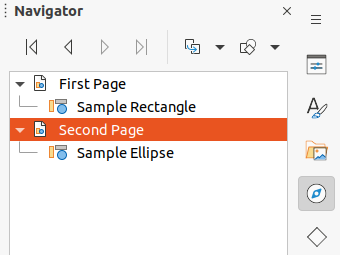
Click on Navigator on the right of the Sidebar to open the Navigator deck (Figure 3).
Figure 1: Draw main window
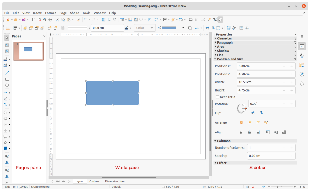
Figure 2: Navigator dialog
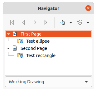
Figure 3: Navigator deck on Sidebar
To quickly select a page for editing so it appears in the Workspace, either select the page in the Pages pane, or go to Page > Navigate on the Menu bar and select one of the options from the submenu:
To First Page –– moves the selection to the first page in the drawing.
To Previous Page –– moves the selection backward to the previous page.
To Next Page –– moves the selection forward to the next page.
To Last Page –– moves the selection to the last page in the drawing.
A new page is inserted into a drawing using one of the following methods. A new page is added after the selected page in the Pages pane, or at the end of the pages if no page is selected.
Go to Page > New Page on the Menu bar.
Right-click in the Pages pane and select New Page from the context menu.
Right-click on the page displayed in the Workspace and select Page > New Page from the context menu.
Go to Page > Insert Page from File on the Menu bar and the Insert File dialog opens. Navigate to the folder where the file is located, select the file, click on Open and then click OK.
Select a page in the Pages pane, then use one of the following methods to insert the duplicate page after the selected page:
Go to Page > Duplicate Page on the Menu bar.
Right-click on a page in the Pages pane and select Copy from the context menu, then right-click in a blank area of the Pages pane and select Paste from the context menu.
When pages are inserted into a drawing, they are automatically named as Page 1, Page 2, and so on in the Pages pane and the Navigator. As the page order is changed, pages are automatically renumbered. However, to easily identify each page, it is recommended to give each page a memorable name.
1) Select a page for renaming in the Pages pane.
2) Rename the selected page using one of the following methods:
Go to Page on the Menu bar and select Rename Page from the submenu.
Right-click on the selected page in the Pages pane and select Rename Page from the context menu.
Right-click on the page displayed in the Workspace and select Page > Rename Page from the context menu.
3) In the Rename Page dialog that opens, type a new name for the page and click OK to save.
Select a page thumbnail in the Pages pane, then click and drag the page thumbnail to change the page order.
Select a page thumbnail in the Pages pane, then go to Page > Move on the Menu bar and select one of the following options:
Page to Start –– moves the selected page to the beginning of the drawing.
Page Up –– moves the selected page up one place in the page order of the drawing.
Page Down –– moves the selected page down one place in the page order of the drawing.
Page to End –– moves the selected page to the end of the drawing.
1) Select a page for deletion in the Pages pane.
2) Delete the selected page using one of the following methods:
Go to Page > Delete Page on the Menu bar.
Right-click on the selected page in the Pages pane and select Delete Page from the context menu.
Right-click on the page displayed in the Workspace and select Page > Delete Page from the context menu.
Note
When deleting pages in a drawing, there is no confirmation of deletion for the selected page.
A master page is a page used as the starting point for other pages in a drawing. It is similar to a page style in Writer or master slide in Impress and controls the basic formatting of all pages based upon it. A drawing with multiple pages can have more than one master page so that a different look can be assigned to separate pages in a drawing, for example title page, contents page, and drawing pages.
A master page has a defined set of characteristics. For example, background objects (such as logos, decorative lines), formatting of text, blocks of standard text, and fields such as page numbering, date, and filename.
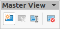
To open the master page view, go to View > Master on the Menu bar. This also opens the Master View toolbar (Figure 4). If this toolbar does not open, go to View > Toolbars > Master View on the Menu bar. To return to normal page mode, click on Close Master View in the Master View toolbar or go to View > Normal on the Menu bar.
Figure 4: Master View toolbar
Each drawing has a default master page. When a drawing has multiple pages, master pages can be created and added to the drawing as follows:
1) Go to View > Master on the Menu bar to open the master page view and the Master View toolbar.
2) Create a new master page using one of the following methods. After creation, the new master page is automatically selected.
Click on New Master in the Master View toolbar.
Go to Page > New Master on the Menu bar.
Right-click in the Pages pane and select New Master from the context menu.
3) Add the required graphic objects, logos, fields, text and so on to the selected master page, then save the drawing.
4) Assign the new master page to a drawing page. See “Assigning master pages” below for more information.
5) If necessary, rename the master page with a meaningful name, see “Renaming master pages” below.
Figure 5: Rename Master Slide dialog
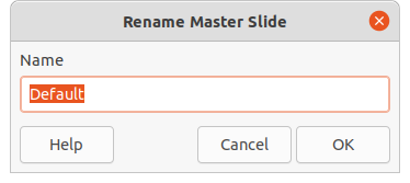
Each new master page created has the default name of Default 1, Default 2, and so on. It is recommended to rename a new master page with a more meaningful name. The default master page that was created when the drawing was first created can also be renamed.
1) Go to View > Master on the Menu bar to open the master page view and the Master View toolbar.
2) Open the Rename Master Slide dialog (Figure 5) using one of the following methods:
Click on Rename Master in the Master View toolbar.
Right-click on a master page in the Pages pane and select Rename Master from the context menu.
3) Enter a meaningful name for the master page in the Name text box, then click OK to save the changes and close the Rename Master Slide dialog.
When a drawing has more than one master page, different master pages can be assigned to different pages.
1) Go to View > Normal on the Menu bar.
2) In the Pages pane, select the page to assign a master page to it.
Figure 6: Available master Slides dialog
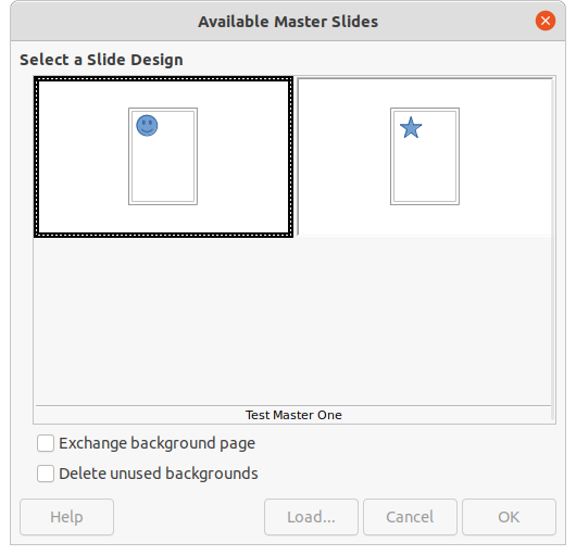
3) Right-click on the page in the Workspace and select Change Slide Master from the context menu to open the Available Master Slides dialog (Figure 6).
4) Select a master page design for the selected page in Select a Slide Design.
5) If necessary, select Exchange background page to use the selected master page for all pages in the drawing.
6) If necessary, select Delete unused backgrounds to delete any master pages shown in Select a Slide Design that have not been assigned to a page.
7) Click OK to assign the selected master page and close the Available Master Slides dialog.
The default master page created when the drawing was first created cannot be deleted. Also, if the drawing only uses one named master page, then that named master page cannot be deleted. Deleting master pages is only available when there is more than one master page in a drawing.
1) Go to View > Master on the Menu bar to open the master page view and the Master View toolbar.
2) Delete a master page using one of the following methods:
Select and right-click on a master page in the Pages pane, then select Delete Master from the context menu.
Click on Delete Master in the Master View toolbar.
Go to Page > Delete Master on the Menu bar.
Note
The deletion of the master page is immediate and there is no confirmation.
1) Go to View > Master on the Menu bar to open the master page view and the Master View toolbar.
2) Go to Insert > Field on the Menu bar and select a field type from the options available on the submenu.
The field types that are available for insertion as follows:
Date (fixed) –– inserts the current date into the master page as a fixed field. The date is not automatically updated.
Date (variable) –– inserts the current date into the master page as a variable field. The date is automatically updated each time the file is opened.
Time (fixed) –– inserts the current time into the master page as a fixed field. The time is not automatically updated.
Time (variable) –– inserts the current time into the master page as a variable field. The time is automatically updated each time the file is opened.
Author –– inserts the first and last names listed in the LibreOffice user data into the active page. Go to Tools > Options > LibreOffice > User Data (macOS LibreOffice > Preferences > LibreOffice > User Data) on the Menu bar to enter user data details.
Figure 7: Page Properties dialog
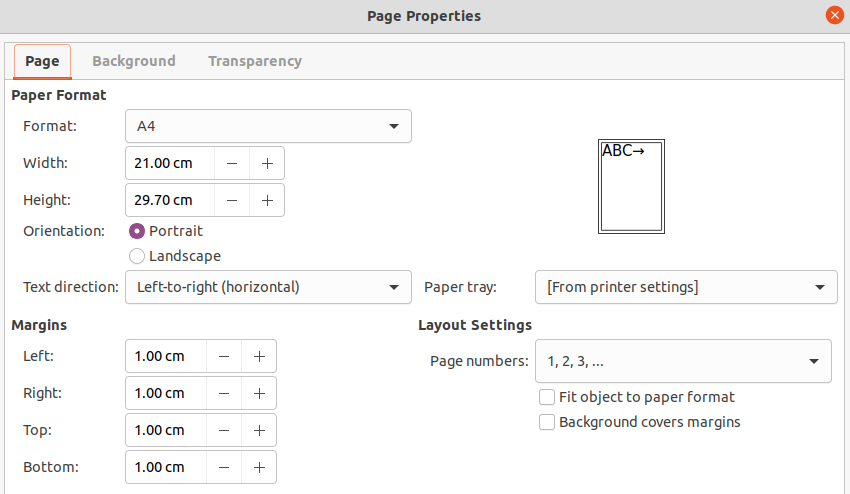
Page Number –– inserts the page number into every page of the drawing. To change the number format, go to Page > Page Properties on the Menu bar to open the Page Properties dialog (Figure 7). Click on the Page tab and select a number format from the drop-down list in Layout Settings.
Page Title –– inserts the page title. A page title is created in Normal view by going to Page > Rename Page on the Menu bar and entering a title in the Name text box in the Rename Page dialog that opens.
Page Count –– inserts the total number of pages in a drawing.
File Name –– inserts the name of the active file. The name only appears after the file has been saved.
1) Click on a field to select it and display the selection handles.
2) Double click on the field contents to select the text.
3) Edit the field format using one of the following methods:
Go to Edit > Fields... on the Menu bar to open the Edit Field dialog (Figure 8), then select format option(s) and click OK to save the changes.
Right-click on the selected field contents and select an option from the context menu.
4) Click in a blank area of the master page to deselect the field.
Note
The options available in the Edit Field dialog change to match the field type that has been selected for editing.
Figure 8: Edit Field dialog
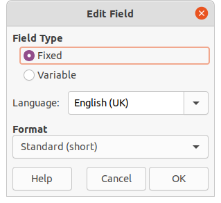
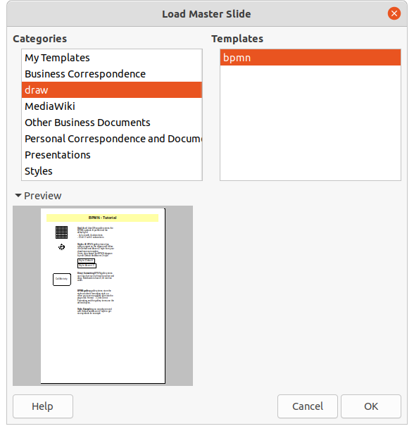
Figure 9: Load Master slide dialog
Master pages from templates available in LibreOffice can be loaded into a drawing and used. If the master pages from a template use a different page size, the master pages loaded into a drawing are adapted to the page size used in the drawing. This may cause some objects to be stretched or incorrectly positioned when adapted to fit the drawing page size.
1) Go to View > Master on the Menu bar to open the master page view and the Master View toolbar.
2) Right-click on a master page displayed in the drawing and select Change Master Slide from the context menu to open the Available Master Slides dialog.
3) Click on Load… in the Available Master Slides dialog to open the Load Master Slide dialog (Figure 9).
4) Chose a template category from list displayed in Categories.
5) Choose a template from the list displayed in Templates. Click Preview to display a preview of the selected template.
6) Click OK to close the Load Master Slide dialog and the Available Master Slides dialog opens displaying the template in Select a Slide Design.
7) Select the master page design required in Select a Slide Design.
8) If necessary, select Exchange background page to use the selected master page for all pages in the drawing.
9) If necessary, select Delete unused backgrounds to delete any master pages shown in Select a Slide Design that have not been assigned to a page.
10) Click OK to assign the selected master page to a drawing page and close the Available Master Slides dialog.
A template is a special type of drawing that is used as a basis to create a drawing. For example, a template can include a company logo, name and information on the first page of a drawing with the remaining pages in a drawing only showing the company logo and name. Templates can contain anything that regular drawings can contain, such as text, graphics, a set of styles, and so on.
All document types created using LibreOffice are based on templates. If a template is not specified when a new document is started, then the default template for that type of document is used. This default template uses a set of properties that are hard coded in LibreOffice. If necessary, the default template for drawings that is hard coded in LibreOffice can be changed, see “Default template” on page 1 for more information.
For more information on templates and obtaining templates from other sources, see the Getting Started Guide.
Draw does not have any predefined templates when it is installed on a computer. However, templates can be created using methods described in the following sections. Templates can also be installed that have been obtained from other sources, see "Importing templates" on page 1 for more information.
1) Open a drawing to use as a basis for a template, or open and edit a template to use as a basis for a new template.
2) Add any extra content and styles or edit the content and styles in the drawing.
3) Open the Save As Template dialog (Figure 10) using one of the following methods:
Go to File > Templates > Save As Template on the Menu bar.
Click on the triangle ▼ to the right of Save on the Standard toolbar and select Save as Template from the drop-down menu.
4) Enter a name for the template in the Template Name text box.
5) Select a category for the template in the Template Category box.
Figure 10: Save As Template dialog
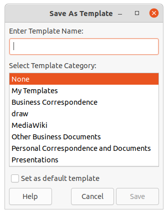
6) If the template is to be used as the default template in Draw, then select the option Set as default template.
7) Click on Save to save the template and close the dialog.
Alternatively, the command Save As can be used to save the drawing as a template using the following procedure:
1) Go to File > Save As on the Menu bar to open the Save as dialog.
2) Navigate to the LibreOffice templates folder. Actual location of the LibreOffice template folder depends on the computer system and setup.
3) Enter a filename using the extension .otg.
4) Select ODF Drawing Template (.otg) as the file type.
5) Click on Save to save the template and close the dialog.
Note
When saving a drawing as a template, the template must be saved in the LibreOffice templates folder for the template to be recognized and found by the LibreOffice Template Manager.
Instead of using the default settings in LibreOffice to create a new drawing, a drawing can be created from a template.
Open LibreOffice and create a new drawing from a template displayed in the Start Center using one of the following methods:
Click on Templates in the Start Center to open a display of available templates for all LibreOffice applications. Click on a template and a new document opens using the relevant LibreOffice module application for the template.
Click on the triangle ▼ to the right of Templates in the Start Center, then select Draw Templates to display only the available templates for LibreOffice Draw. Click on a template and a new drawing opens using LibreOffice Draw.
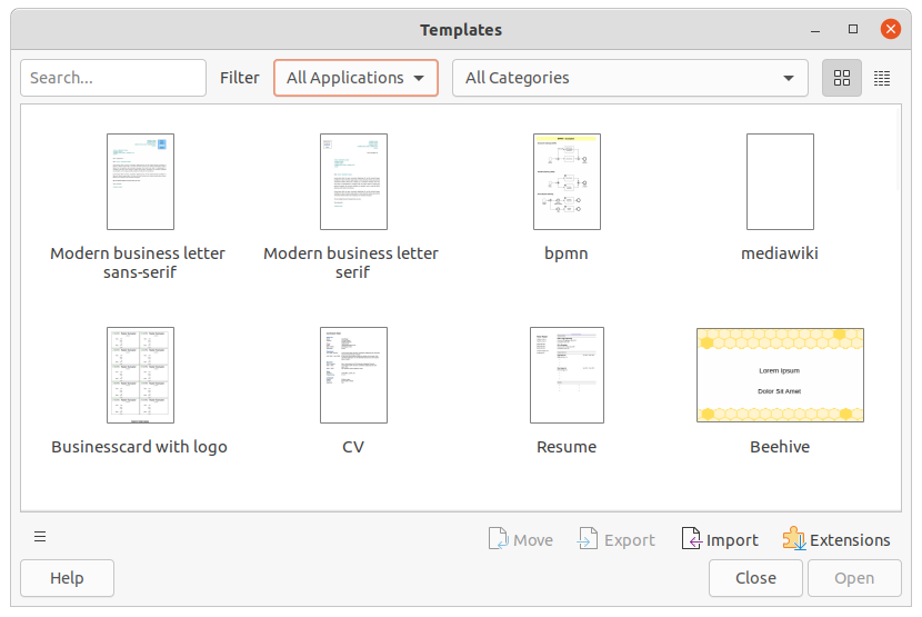
Instead of using the default settings in LibreOffice to create a new drawing, the Templates dialog (Figure 11) can be used as follows:
1) Use one of the following methods to open the Templates dialog:
Go to File > New > Templates on the Menu bar.
Go to File > Templates > Manage Templates on the Menu bar.
Use the keyboard short cut Ctrl+Shift+N (macOS ⌘+Shift+N).
2) In the Filter drop-down lists, select Draw as the application and the template category required for the new drawing.
3) Select a template from the options available in the preview box.
4) Click Open or double click on the template to create a new drawing using the selected template and close the Template dialog.
5) Go to File > Save As on the Menu bar and save the new drawing as a file using the extension .odg.
Figure 11: Templates dialog
If a new drawing is created without selecting a template, LibreOffice creates the drawing using a set of properties that are hard coded in LibreOffice. However, any drawing template can be used as the default template, but the template must be located in the templates folders used for LibreOffice applications and categories.
1) Use one of the following methods to open the Templates dialog:
Go to File > New > Templates on the Menu bar.
Go to File > Templates > Manage Templates on the Menu bar.
Use the keyboard short cut Ctrl+Shift+N (macOS ⌘+Shift+N).
2) In the Filter drop-down lists, select Drawings and then the template category.
3) Select a template from the templates displayed in the preview box.
4) Right-click on the template and select Set as default from the context menu. There is no confirmation that the selected template has become the default template for new drawings. The default template is indicated by check mark at the top left corner of the template icon.
5) Click on Cancel to close the Templates dialog. The next time a new drawing is created, it will use the new default template.
Note
If a new drawing is suitable to use as the default template, then the drawing must be saved as a template first before it can be used as the default template. See “Creating drawing templates” on page 1 for more information.
1) Use one of the following methods to open the Templates dialog:
Go to File > New > Templates on the Menu bar.
Go to File > Templates > Manage Templates on the Menu bar.
Use the keyboard short cut Ctrl+Shift+N (macOS ⌘+Shift+N).
2) In the Filter drop-down lists, select Drawings and then the template category.
3) Right-click on the default template. The default template is indicated by check mark at the top left corner of the template icon.
4) Select Reset Default from the context menu. There is no confirmation that Draw has been reset to using LibreOffice default properties for creating a new drawing. The check mark is removed from the template icon.
5) Click on Cancel to close the Templates dialog. The next time a new drawing is created, it will use the LibreOffice default properties.
Note
Templates that were supplied with LibreOffice cannot be edited or deleted. Only templates that have been created using LibreOffice or imported into LibreOffice can be edited or deleted.
Template styles and template content can be edited, and then, if necessary, reapplied to drawings that were created from that template. Any content in the drawing, but not included in the template, cannot be reapplied.
1) Use one of the following methods to open the Templates dialog:
Go to File > New > Templates on the Menu bar.
Go to File > Templates > Manage Templates on the Menu bar.
Use the keyboard short cut Ctrl+Shift+N (macOS ⌘+Shift+N).
2) Select a template that was created using LibreOffice or imported into LibreOffice.
3) Right-click on the selected template and select Edit from the context menu. The template opens in Draw.
Note
If the Edit option is greyed out, then the selected template is part of the LibreOffice installation and cannot be edited.
4) Edit the template as any other drawing.
5) Go to File > Save on the Menu bar or use the keyboard shortcut Ctrl+S (macOS ⌘+S) to save the template.
6) Alternatively, save the edited template as a new template. See “Creating drawing templates” on page 1 for more information.
The next time a drawing is opened created from the modified template, a confirmation dialog opens asking to update the styles in the drawing to the formatting used in the modified template.
Click Update Styles to update any styles in the drawing that have been changed in the template and close the confirmation dialog.
Click Keep Old Styles so that styles in the drawing that have been changed in the template are not updated. The confirmation dialog closes and will not appear again the next time the document is opened.
Note
If Keep Old Styles is selected, the drawing is no longer connected to the template. However, the template is still listed under File > Properties > General. To reconnect the document to the template, the template has to be reassigned. See “Changing templates assigned to drawings” below for more information.
If necessary, the template associated with a drawing can be changed to a different template, or reassign the original template for the drawing back to the drawing.
To manually change or reassign a template, create a new drawing from the required template and copy the contents from the old drawing into the new drawing.
Download the Template Changer extension from the LibreOffice website at https://extensions.libreoffice.org/en/extensions/show/template-changer and install it into LibreOffice. Restart LibreOffice to activate the extension. Open the drawing and use File > Templates > Change template (current document) on the Menu bar to change the template. For more information, see the Getting Started Guide.
LibreOffice can only locate templates that are in LibreOffice template folders (categories). New LibreOffice template categories can be created and used to organize templates, for example creating separate categories for different projects or clients. Templates can also be imported and exported.
Tip
The location of LibreOffice template folders varies with the computer operating system. To learn where the template folders are stored on a computer, go to Tools > Options > LibreOffice > Paths (macOS LibreOffice > Preferences > LibreOffice > Paths) on the Menu bar.
1) Use one of the following methods to open the Templates dialog:
Go to File > New > Templates on the Menu bar.
Go to File > Templates > Manage Templates on the Menu bar.
Use the keyboard short cut Ctrl+Shift+N (macOS ⌘+Shift+N).
2) In the Filter drop-down lists, select Drawings as the application.
3) Click on Tools in the bottom left corner and select New Category from the context menu.
4) Enter a name in the Enter category name text box in the dialog that opens.
5) Click OK to save the new category in LibreOffice and close the dialog.
Template categories supplied with LibreOffice cannot be renamed. Only template categories that have been created can be renamed.
1) Use one of the following methods to open the Templates dialog:
Go to File > New > Templates on the Menu bar.
Go to File > Templates > Manage Templates on the Menu bar.
Use the keyboard short cut Ctrl+Shift+N (macOS ⌘+Shift+N).
2) In the Filter drop-down lists, select Drawings as the application and the template category for renaming.
3) Click on Tools in the bottom left corner and select Rename Category from the context menu.
4) Enter a name in the Enter category name text box in the dialog that opens.
5) Click OK to save the renamed category in LibreOffice and close the dialog.
Note
If an attempt to rename a category that was installed with LibreOffice is made, an error message opens stating that the category cannot be renamed.
Template categories supplied with LibreOffice cannot be deleted. Only template categories that have been created manually can be deleted.
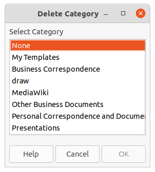
Figure 12: Delete Category dialog
1) Use one of the following methods to open the Templates dialog:
Go to File > New > Templates on the Menu bar.
Go to File > Templates > Manage Templates on the Menu bar.
Use the keyboard short cut Ctrl+Shift+N (macOS ⌘+Shift+N).
2) Click on Settings and select Delete Category from the context menu.
3) Select the category in the Delete Category dialog (Figure 12) that opens.
4) Click OK to delete the selected category and close the Delete Category dialog.
5) Click Yes to confirm the deletion of the category.
Note
If an attempt to delete a category that was installed with LibreOffice is made, an error message opens stating that the category cannot be deleted.
A template is moved from one template category to another template category as follows:
1) Use one of the following methods to open the Templates dialog:
Go to File > New > Templates on the Menu bar.
Go to File > Templates > Manage Templates on the Menu bar.
Use the keyboard short cut Ctrl+Shift+N (macOS ⌘+Shift+N).
2) In the Filter drop-down lists, select Drawings as the application and the template category where the template is located.
3) Select the template that is going to be moved.
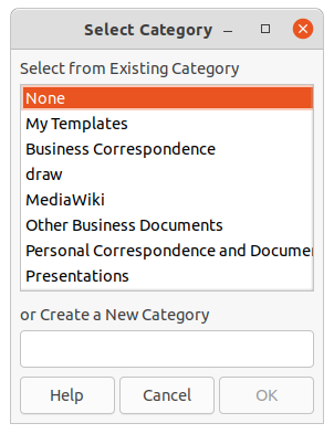
4) Click on Move and the Select Category dialog (Figure 13) opens.
5) Select a category from Select from Existing Category or enter a name for a new category in Create a New Category.
6) Click OK to move the template to the selected category and close the Select Category dialog.
Figure 13: Select Category dialog
Templates can be downloaded from many sources, including the official LibreOffice template repository using the Extension Manager. Save the template anywhere on a computer, then import the template into LibreOffice as follows:
1) Use one of the following methods to open the Templates dialog:
Go to File > New > Templates on the Menu bar.
Go to File > Templates > Manage Templates on the Menu bar.
Use the keyboard short cut Ctrl+Shift+N (macOS ⌘+Shift+N).
2) Click on Import and the Select Category dialog opens.
3) Select a category from Select from Existing Category or enter a name for a new category in Create a New Category.
4) Click OK and a file browser window opens.
5) Navigate to the folder containing the template, select the template and click Open. The file browser closes and the template appears in the selected template category in the Templates dialog.
Note
For more information about using the Extension Manager to import templates, see the Getting Started Guide.
Export a template from a template category to another location in a computer or network as follows:
1) Use one of the following methods to open the Templates dialog:
Go to File > New > Templates on the Menu bar.
Go to File > Templates > Manage Templates on the Menu bar.
Use the keyboard short cut Ctrl+Shift+N (macOS ⌘+Shift+N).
2) In the Filter drop-down lists, select Drawings as the application and the template category where the template is located.
3) Select a template for export and click Export to open a file browser window.
4) Navigate to the folder to export the template into.
5) Click OK and the exported template appears in the selected folder.
6) Click Cancel to close the Templates dialog.
Note
Exporting a template does not remove it from the Templates dialog. The action places a copy of the template in the location specified.
1) Use one of the following methods to open the Templates dialog:
Go to File > New > Templates on the Menu bar.
Go to File > Templates > Manage Templates on the Menu bar.
Use the keyboard short cut Ctrl+Shift+N (macOS ⌘+Shift+N).
2) In the Filter drop-down lists, select Drawings as the application and the template category where the template is located.
3) Right-click on the template for deletion and select Delete from the context menu.
4) Click Yes to confirm the deletion of the template.
5) Click Cancel to close the Templates dialog.
Tip
Press the Delete or Backspace key on the keyboard to delete the selected template in the Templates dialog
Note
Templates that were installed with LibreOffice cannot be deleted. Only templates that have been created after the installation of LibreOffice can be deleted.
Templates can be created and stored anywhere on a computer and then used without involving the Templates dialog. However, some results maybe different from those described above.
Create a drawing from a compatible template by double-clicking the template in a file browser window. The resulting drawing is not associated with (linked to) the template from which it was created. The template is not listed in the properties of the document and any changes to the template cannot be directly applied to the document. For many purposes, this may be what is required.
Create a template from a drawing using File > Save As on the Menu bar and selecting ODF Drawing Template (.otg) as the file type, then saving it anywhere on a computer, for example in a project folder.
The resulting template is visible in the Templates dialog, unless it is imported it or added to the project folder to the locations shown for templates in Tools > Options > LibreOffice > Paths (macOS LibreOffice > Preferences > LibreOffice > Paths). See “Organizing templates” on page 1 and “Importing templates” on page 1 for more information.
Layers in LibreOffice Draw allow assembly of elements in a drawing that are related. Think of layers as individual workspaces that can be hidden from view, prevented from printing, or locked so that changes cannot be made.
Layers do not determine the stacking order of objects on a drawing, except for the Controls layer which is always in front of all other layers. The stacking order of objects on a drawing is determined by the sequence in objects are added. This stacking order can be rearranged by going to Shape > Arrange on the Menu bar.
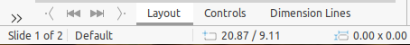
Layers in a drawing are indicated by tabs located at the bottom of the Workspace and above the Status bar. Click on a tab to select a layer. Figure 14 shows the Layout layer has been selected.
Figure 14: Layer tabs in Workspace
Note
When a new layer is added, the layer is added to all pages in a drawing. However, when an object is added to a layer, the object is only added to the selected drawing page.
Note
If an object is to appear on all pages of a drawing (for example, a company logo), add the object to the master page by going to View > Master on the Menu bar. See “Master pages” on page 1 for more information.
In Normal view, LibreOffice Draw provides three default layers that are visible to the user. These default layers cannot be deleted or renamed.
Layout – is the default workspace where objects are normally placed.
Controls – used for form controls that have been assigned an action. Objects on this layer are always in front of objects on other layers. Normally, form controls would not be printed and the Printable option in the Modify Layer dialog has to be deselected.
Dimension Lines – is where the dimension lines are drawn. By switching the layer between show or hide, dimension lines are switched on and off.
Figure 15: Insert Layer dialog
In Master view, LibreOffice provides a single layer, Background objects, that is visible to the user. This layer is used to places objects that appear on every page in a drawing, for example company logo, date, page number, drawing title, and so on.
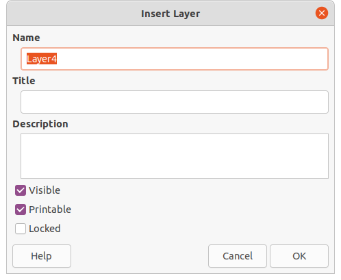
1) Use one of the following methods to open the Insert Layer dialog (Figure 15):
Right-click the layer tab area at the bottom of the Workspace area and select Insert Layer from the context menu.
Go to Insert > Layer on the Menu bar.
2) Enter meaningful names for the layer in the Name and Title text boxes.
3) If necessary, enter a description for the new layer in the Description text box.
4) Select Visible for the layer to be visible in a drawing. When Visible is not selected, the layer is hidden and its name in the layer tab changes color to blue.
5) Select Printable for the layer to print when the drawing is printed. The name of a layer is underlined in the layer tab bar when Printable is NOT selected. For example, not printing a layer is useful if the layer is a draft layer for guides or annotations used in creating the drawing, but this draft layer is not required for the final printed output.
6) Select Locked to prevent any objects on a layer from deletion, editing, or moving. No additional objects can be added to a locked layer. For example, locking a layer is useful when a base plan is to be protected while adding a new layer with other details. The name of a locked layer is changes to italic text in the layer tab bar.
7) Click OK to close the Insert Layer dialog and the new layer automatically becomes active.
1) Use one of the following methods to open the Modify Layer dialog (Figure 16).
Right-click the name tab for the layer at the bottom of the Workspace and select Modify Layer from the context menu.
Figure 16: Modify Layer dialog
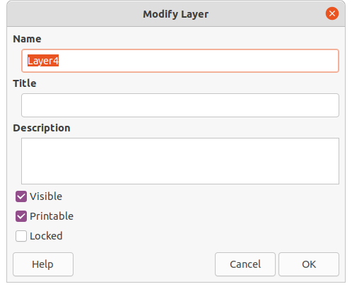
Click on the layer tab to select it, then go to Format > Layer on the Menu bar.
Double click on the layer tab.
2) Make the necessary changes to the attributes for the layer, then click OK to save the changes and close the Modify Layer dialog.
To select a layer, click on the name tab for the layer at the bottom of the Workspace. When a layer is selected it is activated, and any objects added to the drawing are only added to that layer. Form controls are automatically added to the Controls layer and dimension lines are automatically added to the Dimension Lines layer.
If there are several layers in a drawing, a layer tab may not not be visible on the layer tab bar. Use the navigation icons on the left of the layer tab bar to navigate to the layer for selection.
1) Select the layer that is going to be hidden and open the Modify Layer dialog. See “Modifying layers” above for more information.
2) Deselect Visible and click OK. The text on the layer name tab changes color to blue. Any objects placed on a hidden layer are no longer visible on the other layers in the drawing.
3) Alternatively, hold down the Shift key and click on the layer name tab to hide the layer.
1) Select the hidden layer and open the Modify Layer dialog. See “Modifying layers” above for more information.
2) Select Visible and click OK. The text on the layer name tab changes color to the default text color. Any objects placed on a hidden layer are now visible on the other layers in a drawing.
3) Alternatively, hold down the Shift key and click on the name tab of a hidden layer to make the layer visible.
1) Select the layer that is going to be locked and open the Modify Layer dialog. See “Modifying layers” above for more information.
2) Select Locked and click OK. The text on the layer name tab is underlined. Locking a layer prevents any modification of the layer.
3) Alternatively, hold down the Ctrl (macOS ⌘) key and click on the name tab to lock the layer.
1) Select the locked layer and open the Modify Layer dialog. See “Modifying layers” above for more information.
2) Deselect Locked and click OK. The text on the layer name tab is no longer underlined.
3) Alternatively, hold down the Ctrl (macOS ⌘) key and click on the name tab of the locked layer to unlock it.
1) Select the layer that is going to be renamed and open the Modify Layer dialog.
2) Enter a new name in the Name text box. See “Modifying layers” above for more information.
3) Alternatively, right-click on the name tab of the layer and select Rename Layer from the context menu. The text becomes editable allowing the name to be changed. Click outside the tab area to save the change.
4) Alternatively, hold down the Alt key (macOS ⌥) and click on the name tab. The text becomes editable allowing the name to be changed. Click outside the tab area to save the change.
Note
Only layers that have been added to a drawing can be renamed or deleted. The default layers Layout, Controls, Dimension Lines and Background objects cannot be renamed or deleted.
1) Right-click on the name tab of the layer that is going to be deleted and select Delete Layer from the context menu.
2) Confirm the deletion of the layer. The layer and all of the objects on the layer are deleted.
If objects are selected on a layer, the Status bar indicates how many objects are selected. Move these selected objects from one layer to another layer using one of the following methods:
Click and drag the selected objects to the name tab of the destination layer and release the cursor. The position of the moved objects does not change and the layer where the objects have been placed is displayed in the Status bar.
Go to Edit > Cut on the Menu bar or right-click on the selected objects and select Cut from the context menu. Select the destination layer, then go to Edit > Paste on the Menu bar or right-click on the Workspace and select Paste from the context menu. The position of the moved objects does not change and the layer where the objects have been placed is displayed in the Status bar.
Figure 17: Graphic Styles dialog - Dimensioning page
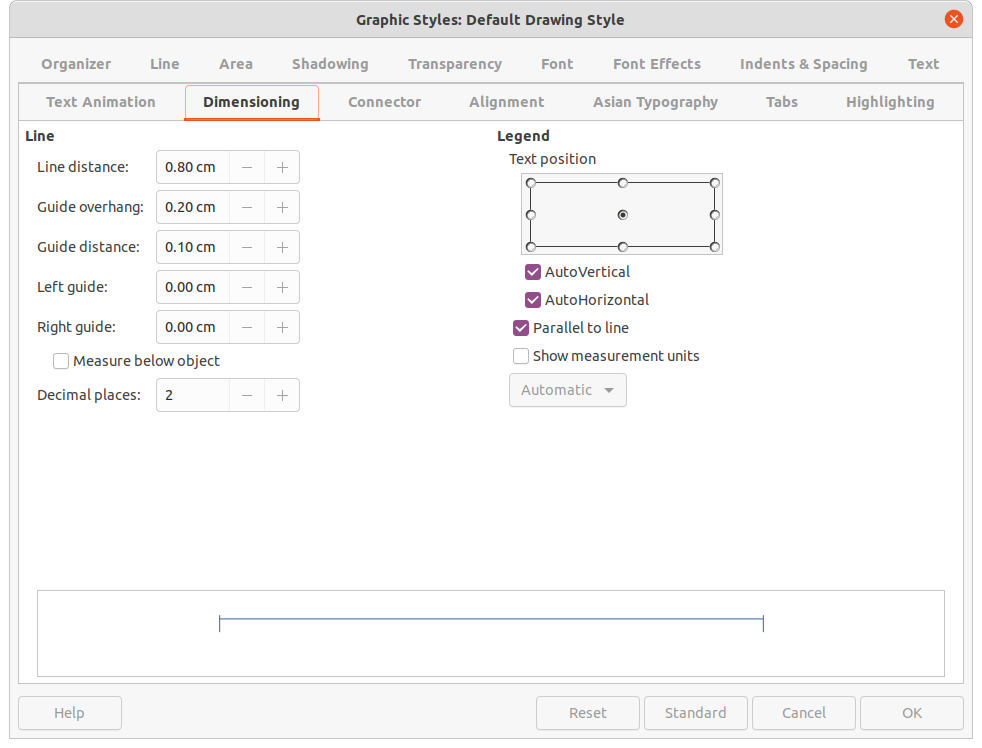
Draw allows objects to be dimensioned and display these dimensions to make a drawing look more like an engineering drawing. When dimensions are created, they are automatically placed on the Dimension Lines layer.
Two ways are available to access the options to configure dimensioning. Both methods use a dialog where the length, measurement, and guide properties of a dimension line can be changed.
1) Open the Graphics Styles dialog (Figure 17) using one of the following methods:
Go to Format > Styles > Edit Styles on the Menu bar.
Click on Show the Styles Sidebar on the Line and Filling toolbar to open the Styles deck on the Sidebar, then right-click on a style and select Modify from the context menu.
Use the keyboard shortcut F11 (macOS ⌘+T) to open the Styles deck on the Sidebar, then right-click on a style and select Modify from the context menu.
Click on Styles on the Sidebar to open the Styles deck, then right-click on a style and select Modify from the context menu.
2) Click on Dimensioning to open the Dimensioning page in the dialog.
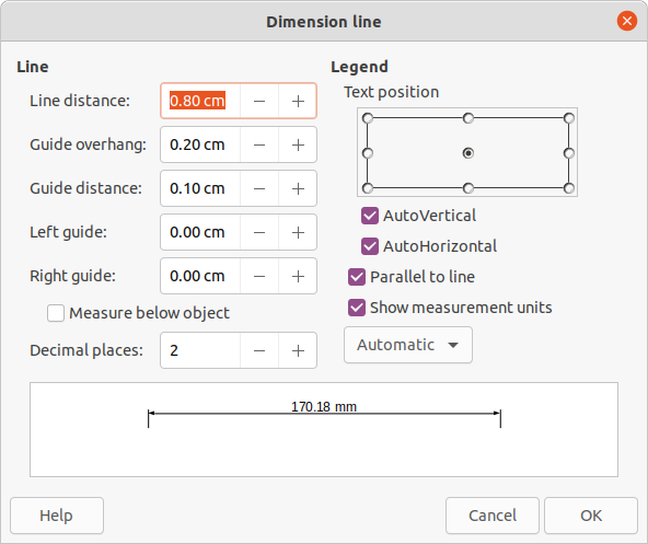
Figure 18: Dimension Line dialog
3) Make the changes required to dimensioning using the various options in the Line and Legend sections on the Dimensioning page.
4) Click OK to save the changes and close the Graphic Styles dialog.
5) To reset the dimensioning options to the default properties of the template, open the Graphics Style dialog as given in Steps 1 and 2 above, then click on Standard.
1) Draw a dimension line. See “Dimensioning objects” on page 1 for more information.
2) Right-click on the dimension line and select Dimensions from the context menu to open the Dimension line dialog (Figure 18).
3) Make the required changes for dimensioning using the various options in the Dimension line dialog.
4) Click OK to save the changes and close the Dimension line dialog.
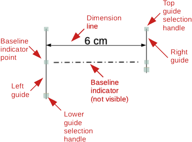
The dimensioning options in the Dimensions page in the Graphics Style dialog and the Dimension Line dialog are as follows. The preview in the dialogs changes as the following options are changed showing how the dimension line will appear in a drawing. An example dimension line is shown in Figure 19.
Line – sets the distances between the dimension line and guides with respect to each other, the dimension baseline and the object. The baseline is not visible in a drawing, but is indicated by baseline points on each of the guides.
Line distance –– specifies the distance between the dimension line and the object or the baseline. A minimum of -10mm to a maximum of 10mm can be entered in the text box. The lower the value, the closer the dimension line is to the object or baseline.
Figure 19: Example dimension line
Guide overhang –– is the distance the guide either extends above the dimension line or is below the dimension line. A minimum of -10mm to a maximum of 10mm can be entered in the text box. Positive values cause the guide overhang to extend above the dimension line. Negative values cause the guide overhang to be below the baseline.
Guide distance –– specifies the length of the right and left guides below the dimension line toward the object. A minimum of -10mm to a maximum of 10mm can be entered in the text box. Positive values extend the guides above the baseline and further away from the object. Negative values extend the guides below the baseline and closer to the object.
Left guide –– specifies the length of the left guide starting at the dimension line. A minimum of -10mm to a maximum of 10mm can be entered in the text box. Positive values extend the guide below the dimension line toward the object. Negative values move the guide away from the object.
Right guide –– specifies the length of the right guide starting at the dimension line. A minimum of -10mm to a maximum of 10mm can be entered in the text box. Positive values extend the guide below the dimension line toward the object. Negative values move the guide away from the object.
Measure below object –– reverses the positions and lengths of the dimension line and guides set in Line options.
Decimal places –– specifies the number of decimal places used for the display of line properties.
Legend – sets the properties of the dimension text.
Text position –– determines the position of the dimension text with respect to the dimension line and the guides. The AutoVertical and AutoHorizontal checkboxes must be empty before a text position can be assigned.
AutoVertical –– determines the optimal vertical position for the dimension text.
AutoHorizontal –– determines the optimal horizontal position for the dimension text.
Parallel to line –– displays, when selected, the text parallel to the dimension line or, when deselected, at 90 degrees to the dimension line.
Show measurement units –– shows or hides the dimension measurement units. A measurement unit can be selected from the drop-down list.
Note
The dimensioning options are linked and stored with the current work page. All the changes that made apply only to this drawing. New drawings are started with the standard properties of Draw. If the dimensioning options are to be used for future drawings, save the drawing as a template.
The guide selection handles at the top and bottom of the guides are used to extend the guides more than the limits of -10mm to 10mm. With reference to the dimension example in Figure 19, the guide selection handles are used as follows:
Top guide selection handles –– select either selection handle and drag the handle to increase or decrease the guide overhang of both guides.
Lower left guide selection handle –– select the left guide selection and drag the handle to increase or decrease of the left guide distance.
Lower right guide selection handle –– select the right guide selection and drag the handle to increase or decrease of the right guide distance.
Tip
When dimensioning objects, it is recommended to use the zoom function, guide lines and snap functions so dimension lines can be accurately placed on an object. See Chapter 3, Working with Objects and Object Points for more information.
1) Click on the triangle ▼ next to the Lines and Arrows icon on the Drawing toolbar to open the Lines and Arrows pop-up toolbar (Figure 20).
2) Click on Dimension Line and the cursor changes to shape, for example to a cross. The shape depends on the computer setup.
3) Position the cursor at one corner of the object, then click and drag the cursor to the other corner of the object to draw the dimension line. To restrict drawing the dimension line in the horizontal or vertical direction, press and hold the Shift key while dragging the cursor.
4) Release the cursor when the other corner of the object is reached and the dimension line is drawn with the dimension automatically added (as shown in Figure 21). The dimension line is also placed automatically on the Dimension Lines layer.
5) To edit the text of the dimension, double-click on an unselected dimension line to enter text edit mode and make any necessary changes. Click outside the dimension line to save the changes.
6) To configure the dimension line, see “Configuring dimensioning” on page 1.
Note
After editing the dimension text, entering text and then deleting text, save the drawing and reopen it to enable automatic measurements for dimensioning.
Figure 20: Lines and Arrows sub-toolbar
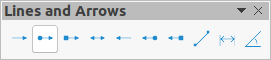
Figure 21: Example of dimensioning an object
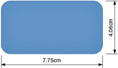
Figure 22: Options LibreOffice Draw General dialog
Note
If drawing to scale, the dimension configuration values in the Graphics Style dialog and the Dimension Line dialog will also be to scale. For example, a value of 10mm in the dialog results in a dimension value of 300mm if the scale has been set to 1:30.
In Draw, the predefined drawing area is called the Workspace is normally Letter or A4 page size depending on the computer setup and the default printer connected to the computer. However, depending on the actual size of the drawn objects, it is often convenient to reduce or enlarge the drawing by scaling (for example 1:10 or 2:1).
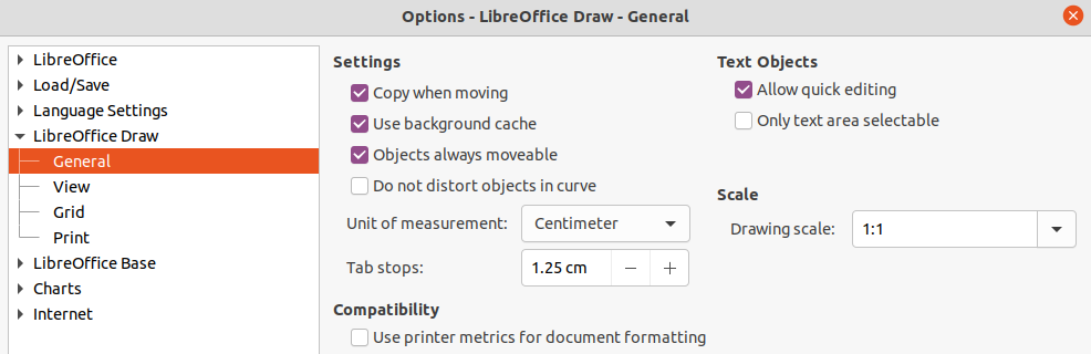
Specify the drawing scale value by going to Tools > Options > LibreOffice Draw > General (macOS LibreOffice > Preferences > LibreOffice Draw > General) to open the Options dialog (Figure 22) and select a value from the Drawing scale drop-down list. The default setting for this option is 1:1. When a change is made to the drawing scale, it is reflected in the rulers at the top and left side of of the Workspace.
Any change in the drawing scale has no effect on the basic drawing operations. Draw automatically calculates the necessary values (for example, dimension lines). The spacing of the grid points is independent of drawing scale as the grid is only a visual drawing aid and not a drawing element.
An increase in scale (for example 1:4) allows large objects to be drawn that would not fit into the paper size for a drawing. A decrease in drawing scale (for example 4:1) allows small objects to be drawn accurately at an increased size and make them easier to understand. Examples of drawing to scale are shown in Figure 23 where all three rectangles are the same size in the drawing.
Figure 23: Examples of drawing to scale
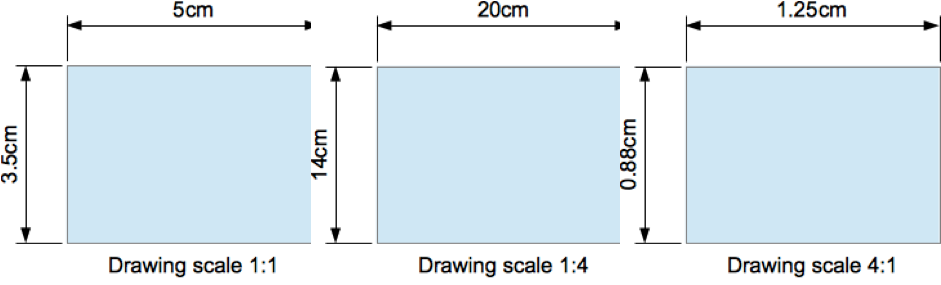
Left rectangle – drawn at the default 1:1 scale and dimensioned.
Center rectangle – drawing scale changed to 1:4 and the dimensions were automatically increased by Draw to reflect the decrease in scale.
Right rectangle – drawing scale changed to 4:1 and the dimensions were automatically decreased by Draw to reflect the increase in scale.
Several views of the same drawing can be opened and used in LibreOffice Draw. These views are displayed in windows that can use different settings for layers (visible, printable and locked), different zoom levels, different origins, or display different pages of the drawing and even use master page and normal page at the same time. However, make sure that the correct view is active when saving a drawing.
To open a new window showing the drawing, go to Window > New Window on the Menu bar. Arrange the windows according to the computer operating system and display preferences. Each window open acts on the same drawing. A change to the drawing in one window is immediately reflected in the other windows.
In each window opened, the filename in the title bar is automatically numbered as shown by the example in Figure 24. If other LibreOffice documents are open at the same time, the list of windows includes all the open documents. The active window has a marker by its filename in the list. Switch between windows by clicking on a name in the list, or by clicking on the window itself if it is visible on the display.
To close a window, go to Window > Close Window on the Menu bar, or use the keyboard shortcut Ctrl+W (macOS ⌘+W), or click on Close in the Menu bar of the window.
Figure 24: Example of multiple windows
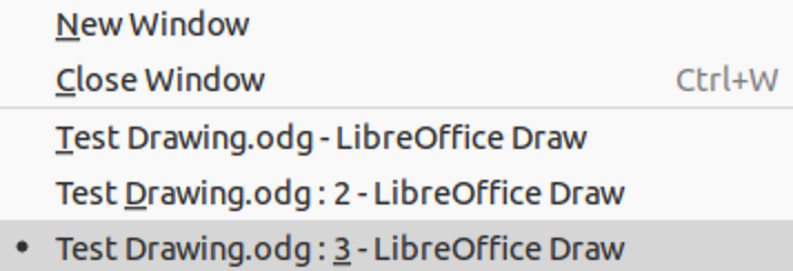
Figure 25: Arrows theme in Gallery deck on Sidebar
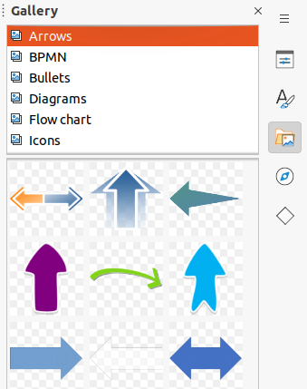
Draw includes several images in the Gallery. These images are grouped into themes (for example Arrows, Bullets, Diagrams, and so on). The Gallery deck on the Sidebar (Figure 25) lists the available themes. Click on a theme and its images are displayed below the theme list.
For a detailed view of the images in a gallery theme, click on Detailed View at the bottom left of the Sidebar.
For an icon view of the images in a gallery theme, click on Icon View at the bottom left of the Sidebar
1) Click on Gallery on the Sidebar, or go to Insert > Media > Gallery on the Menu bar.
2) Select a theme from the available options.
3) Use one of the following methods to place an image into a drawing:
Click on an image in the Gallery deck and drag the image into a drawing.
Right-click on an image and select Insert from the context menu. The image is placed at the center of a drawing.
Right-click on an image and select Copy from the context menu. Paste the image into the drawing and the image is placed at the center of the drawing.
4) Edit the gallery image to the drawing requirements. For more information on editing images and pictures, see Chapter 6, Editing Pictures.
Figure 26: Properties of New Theme dialog - General page
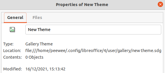
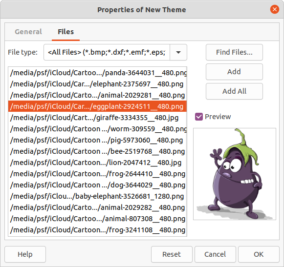
Figure 27: Properties of New Theme dialog - Files page
1) Open the Gallery deck on the Sidebar.
2) Click on New on the Gallery deck to open the Properties of New Theme dialog (Figure 26).
3) Enter a name for the theme in the text box.
4) Click on Files to open the Files page as shown by the example in Figure 27.
5) Click on Find Files to open a Select Path dialog.
6) Browse to the folder that contains the images required and select the folder
7) Click OK to select the files contained in the folder and the Select Path dialog closes. The list of files contained in the folder now appear in the Files page as shown by the example in Figure 27.
8) Select the files required for the new theme and click Add. The selected files disappear from the file list and the images appear in the Gallery.
9) If all the files in the list are to be added, click Add All. All the files disappear from the list and the images appear in the Gallery.
10) Click OK when finished adding files and close the Properties of New Theme dialog. The name of the new theme appears in the Gallery deck.
Note
If a Draw object is added to a theme, the object loses its connection to Draw graphic styles and all properties are set as direct formatting.
1) Right-click on a theme or image in the Gallery and select Delete from the context menu.
2) Click Yes in the confirmation dialog and the image or theme is deleted from the Gallery.
Note
Only themes and images that have added to Draw can be deleted. The themes and images that were included with the installation of LibreOffice cannot be deleted.
Note
An image is a linked file and only the link is deleted from the Gallery. The original image file is not deleted.
All images in the Gallery are linked files. Occasionally, it is beneficial to update a theme that has been added to Draw to make sure that all files are still accessible. Right-click on a theme that has at least one file added to the theme and select Update from the context menu.
To rename a theme that has been added to Draw, right-click on the theme name and select Rename from the context menu.
Note
Only themes and images that have added to Draw can be renamed. The themes and images that were included with the installation of LibreOffice cannot be renamed.
Draw (like all LibreOffice components) uses colors grouped into color palettes. Colors can be created to suit drawing requirements. All custom colors created are placed in the custom color palette. The following explains the color models that can be used to create a custom color.
RGB –– stands for Red, Green, Blue. The RGB color model is based on the additive color model of light waves and is designed for electronic displays and computers. This means, the more color added, the closer a color moves towards white. RGB is created using scales from 0 to 255. This means that black is when R=0, G=0, and B=0 and white is when R=255, G=255, and B=255. LibreOffice uses the RGB color model internally for printing in all of its software modules.
CMYK –– stands for Cyan, Magenta, Yellow, Key (Black). It is a subtractive color model where colors are subtracted to get to white. It is mainly used in printing, which is why the ink cartridges for a printer are labeled CMYK. CMYK works on a scale of 0 to 100. If C=100, M=100, Y=100, and K=100, the color produced is black. If C=0, M=0, Y=0, and K=0, the color produced is white.
HSB –– stands for Hue, Saturation, Brightness. HSB values are an alternative representation of the RGB color model and was designed to be more closely aligned with the way human vision perceives color-making attributes. Use HSB values to fine tune any custom colors that are created.
Tip
More information on color models and color values can be found at https://en.wikipedia.org/wiki/Color_model.
When changing colors in objects, color palettes are used to select colors. These color palettes are installed with LibreOffice and are used in all the LibreOffice modules. Using these color palettes is similar across all types of objects, but accessing the color palettes does vary according to the type of object selected.
Although LibreOffice includes tools to precisely specify a color, it also includes a Color Bar (Figure 28) that allows the area fill, border, or line color of an object to be quickly changed in a drawing.
1) Select an object in the drawing.
2) Go to View > Color Bar on the Menu bar to open the Color Bar. When the Color Bar opens, it is labeled Color Palette.
3) Left click on a color to change the area fill color or right-click on a color to change the border or line color of a selected object.
Figure 28: Color Bar (Color Palette)
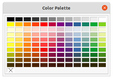
Figure 29: Area dialog - Area Color page
4) Left click on the X box in the bottom left corner of the Color Bar to remove the color from an object fill, or right-click on the X box in the bottom left corner of the Color Bar to remove the color from an object border,
5) To close the Color Bar, go to View > Color Bar on the Menu bar and deselect Color Bar.
Note
The colors available in the Color Bar are from the Standard color palette that is part of the LibreOffice installation.
1) Select an object in the drawing.
2) Open the Area dialog (Figure 29) using one of the following methods:
Go to Format > Area on the Menu bar.
Right-click on the object and select Area from the context menu.
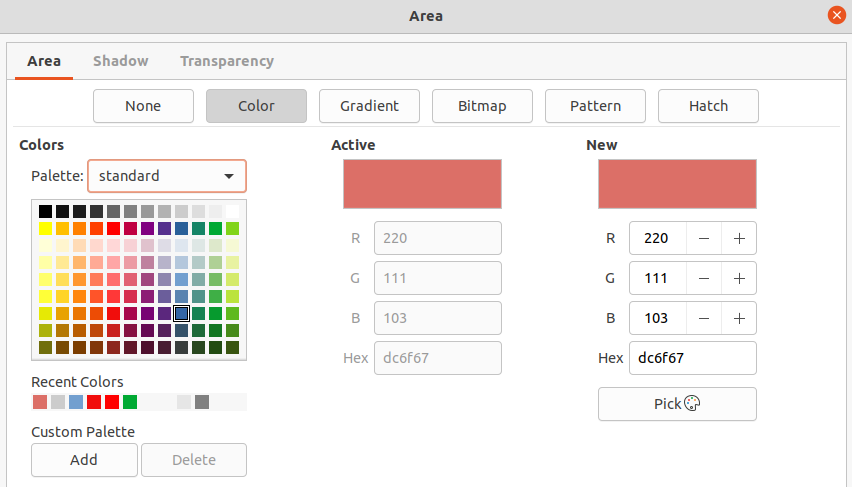
3) Click on Area, then click on Color to open the Color page.
4) In Colors, select a color palette from the Palette drop-down list.
5) Click on a color from the ones displayed in the color palette, or select a color that has been previously used from Recent Colors.
6) Click OK to save the changes and close the Area dialog. The selected fill color appears in the selected object.
1) Select an object in the drawing.
2) Open the Area panel in the Properties deck on the Sidebar (Figure 30).
3) Select Color from the Fill: drop-down list.
4) Click on the triangle ▼ on the right of Fill Color to open the palette last used.
Figure 30: Area panel in Properties deck on Sidebar
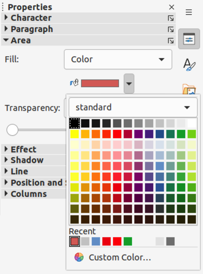
5) Select a color palette to use from the available palettes in the drop-down list.
6) Click on a color from the colors displayed in the color palette, or select a color that has been previously used from those displayed in Recent. The color palette closes and the selected fill color is applied to the object.
1) Select an object in the drawing.
2) Click on the triangle ▼ to the right of Fill Color on the Line and Filling or Draw toolbar to open the last color palette used.
3) Select a color palette to use from the Line Color drop-down list.
4) Click on a color from the colors displayed in the color palette, or select a color that has been previously used from those displayed in Recent. The color palette closes and the selected fill color is applied to the selected line.
1) Select a line or an object in the drawing.
2) Open the Line dialog (Figure 31) using one of the following methods:
Go to Format > Line on the Menu bar.
Right-click on the line or object and select Line from the context menu.
3) Click on Line to open the Line page.
4) Click on the triangle ▼ to the right of Color to open the last color palette used.
5) Select a color palette to use from the available palettes in the drop-down list.
Figure 31: Line dialog - Line page - Color
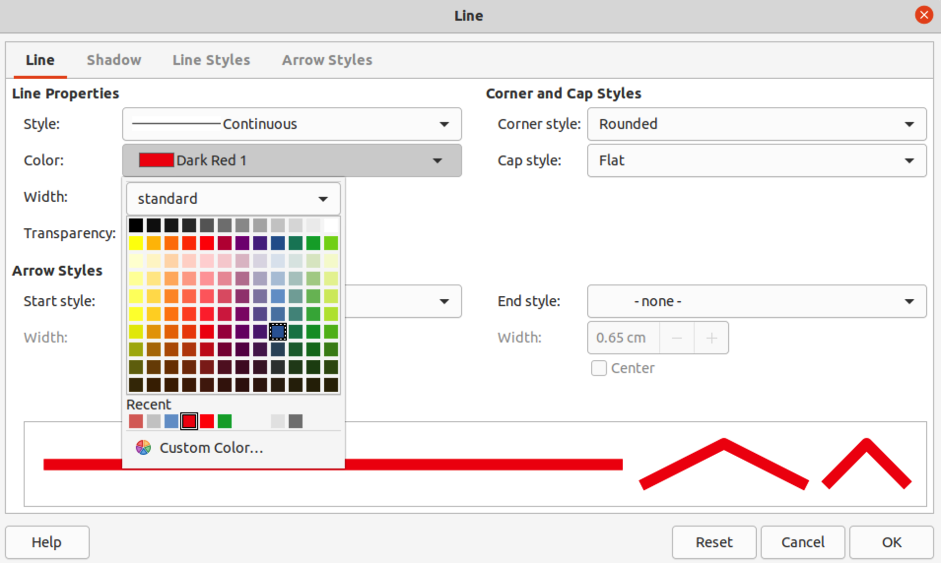
Figure 32: Line panel in Properties deck on Sidebar
6) Click on a color from the colors displayed in the color palette, or select a color that has been previously used from those displayed in Recent. The color palette closes and the selected line color is applied to the line or object border.
7) Click OK to save the color change and close the Line dialog.
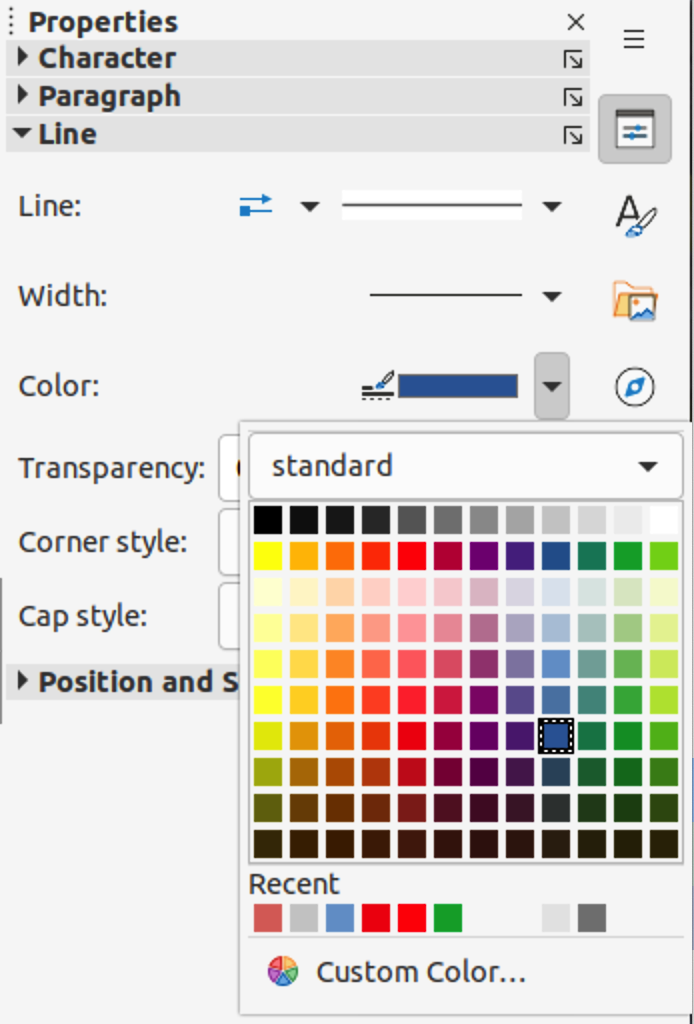
1) Select a line or an object in the drawing.
2) Open the Line panel in the Properties deck on the Sidebar (Figure 32).
3) Click on the triangle ▼ to the right of Color to open the palette last used.
4) Select a color palette to use from the available palettes in the drop-down list.
5) Click on a color from the colors displayed in the color palette, or select a color that has been previously used from those displayed in Recent. The color palette closes and the selected line color is applied to the line or object border.
1) Select a line or object in the drawing.
2) Click on the triangle ▼ to the right of Line Color on the Line and Filling or Draw toolbar to open the last color palette used.
3) Select a color palette to use from the available palettes in the drop-down list.
4) Click on a color from the colors displayed in the color palette, or select a color that has been previously used from those displayed in Recent. The color palette closes and the selected line color is applied to the line or object border.
Figure 33: Character dialog - Font Effects page - Color
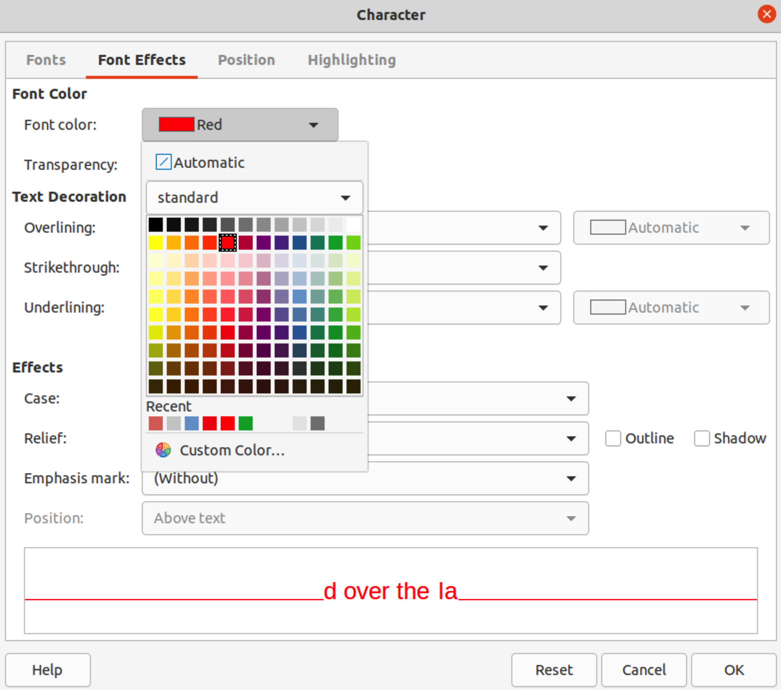
Changing text color is very similar to changing the color of an area fill, object border, or line. The Text Formatting toolbar automatically opens and replaces the Line and Filling toolbar when text is selected in a drawing. If the Text Formatting toolbar does not appear, go to View > Toolbars on the Menu bar and select Text Formatting.
1) Select the text in a text box or object and make sure the text is highlighted.
2) Open the Character dialog (Figure 33) using one of the following methods:
Go to Format > Character on the Menu bar.
Right-click on the highlighted text and select Character from the context menu.
3) Click on Font Effects to open the Font Effects page.
4) Click on the triangle ▼ to the right of Font Color to open the last color palette used.
5) Select a color palette to use from the available palettes in the drop-down list.
6) Click on a color from the colors displayed in the color palette, or select a color that has been previously used from those displayed in Recent. The color palette closes and the selected color is applied to the selected text.
7) Click OK to save the color change and close the Character dialog.
1) Select the text in a text box or object and make sure the text is highlighted.
Figure 34: Character panel in Properties deck on Sidebar
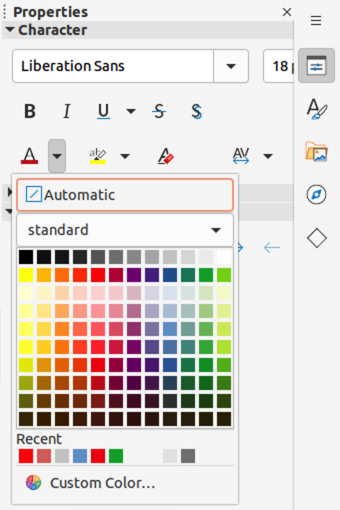
2) Open the Character panel in the Properties deck on the Sidebar (Figure 34).
3) Click on the triangle ▼ to the right of Font Color to open the color palette last used.
4) Select a color palette to use from the available palettes in the drop-down list.
5) Click on a color from the colors displayed in the color palette, or select a color that has been previously used from those displayed in Recent. The color palette closes and the selected color is applied to the selected text.
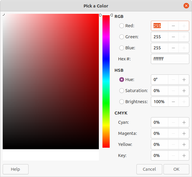
1) Select the object or text and open the Pick a Color dialog (Figure 35) using one of the following methods:
Open the Area dialog, then click on Color to open the Color page and click on Pick.
Open the Area section in Properties deck on the Sidebar, click on the triangle ▼to the right of Fill Color to open the color palette and click on Custom Color at the bottom of the color palette.
Open the Line dialog, then open a color palette in Color and click on Custom Color at the bottom of the color palette.
Open the Line section in Properties deck on the Sidebar, click on the triangle ▼to the right of Line Color to open the color palette and click on Custom Color at the bottom of the color palette.
Open the Character dialog, then open a color palette in Font color and click on Custom Color at the bottom of the color palette.
Figure 35: Pick a Color dialog
Open the Character panel in Properties deck on the Sidebar, click on the triangle ▼to the right of Font Color to open the color palette and click on Custom Color at the bottom of the color palette.
2) Select a color range in the vertical color bar on in the Pick a Color that approximately matches the custom color being created.
3) Click and drag the small target circle in the color box until the color matches the custom color required. The values for RGB, HSB and CMYK change as the small target circle is dragged around the color box. This helps in creating the exact color if these color values are known.
4) Alternatively, if the color values or hex number are known, enter these values in the appropriate text box. The values in all the text boxes changes to match the new values. For example, enter HSB values, the RGB, CMYK and Hex values also change to match.
5) Click OK to save the changes and close the Pick a Color dialog.
Note
When using the Line or Character dialog to open the Pick a Color dialog, the custom color created cannot be saved into the Custom color palette or renamed with a more meaningful name. The custom color created is named using the hex value that is displayed in the Pick a Color dialog. Only the Area dialog has the ability to rename custom colors and save custom colors into the Custom palette.
Note
LibreOffice uses the RGB color model for printing in color. The RGB values of a selected color are displayed below the preview boxes.
1) Open the Area dialog and click on Color to open the Color page.
2) In New, enter the RGB values or, if known, the Hex value into the text boxes. The color changes in the preview box to match the values entered.
3) Alternatively, in New, use the minus and plus signs for the RGB values to decrease or increase the values. The color changes in the preview box to match the values entered.
4) Click OK to change the color and close the Area dialog.
If necessary, add a custom color to the Custom color palette using the Area dialog as follows:
1) Make sure the Area dialog is open at the Color page.
2) Select the custom color that is displayed in Recent Colors.
3) Click on Add to open a Name dialog.
4) Enter a new name for the color in the text box.
5) Click OK to save the changes and close the Name dialog. The custom color appears in the Custom palette.
6) Click OK to close the Area dialog.
Only a custom color can be renamed using the Area dialog as follows:
1) Make sure the Area dialog is open at the Color page.
2) Select the custom color that is displayed in the Custom color palette.
3) Click on Add to open a Name dialog.
4) Enter a new name for the color in the text box,
5) Click OK to save the changes and close the Name dialog. The custom color appears in the Custom palette.
6) Click OK to close the Area dialog.
Note
Renaming a custom color does not actually rename the custom color, but adds the custom color to the Custom palette with a new name.
Note
It is important to use a memorable names for custom colors so that they can be easily recognized in the Custom palette. By default, a custom color is given a hex number, which makes it difficult identifying colors when there is more than one custom color.
Only a custom color can be deleted using the Area dialog as follows:
1) Make sure the Area dialog is open at the Color page.
2) Select the custom color that is displayed in the Custom color palette.
3) Click on Delete. There is no confirmation given when deleting custom colors.
4) Click OK to close the Area dialog.
In LibreOffice, Bézier curves can be used in a drawing. A curve is defined by means of a start point, an end point, and, where necessary, control points. For points on the curve the terms nodes or anchors are often used. For more information and an explanation of the mathematical background of Bézier curves, see https://en.wikipedia.org/wiki/Bézier_curve.
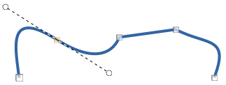
Bézier curves are very useful for experimenting with the shape and form of curves. In point mode the curve alignment can be changed by dragging the points with the cursor. In the example shown in Figure 36, the curve leaves the start point P0 in the direction of the first control point P1 and arrives at the end point P3 from the direction of the second control point P2. The more distant a control point is from the start or end point, the smaller the curvature at that point.
1) Click on Curve in the Curves and Polygons panel in the Shapes deck on the Sidebar or in the Drawing toolbar.
2) Click at the start point for the curve and drag the cursor to the approximate position of the end point for the curve.
3) Release the cursor and drag the end point of the curve to its end position.
4) Double-click when the end position of the curve is reached and a curve is drawn. The arc of the curve is determined by the distance dragged to create the end point.
Figure 36: Example of a Bézier curve
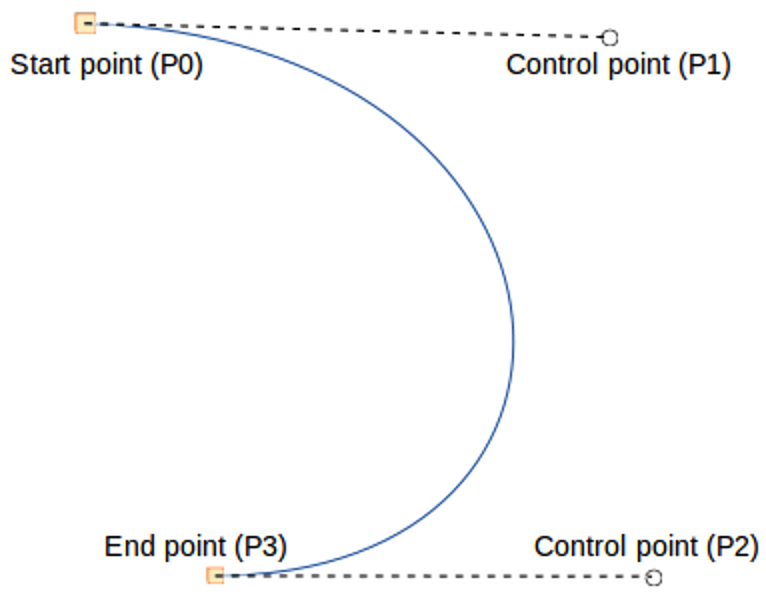
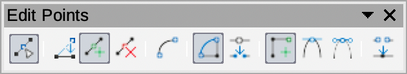
Figure 37: Edit Points toolbar
5) Switch to points mode using one of the following methods:
Go to Edit > Points on the Menu bar.
Click on Points on the Standard toolbar.
Use the keyboard shortcut F8.
6) Open the Edit Points toolbar (Figure 37) using one of the following methods. The Edit Points toolbar does not become visible until a point has been selected on a curve.
Go to View > Toolbars on the Menu bar and select Edit Points.
Click on Points on the Standard toolbar.
Use the keyboard shortcut F8.
If added to the toolbar, click on Points on the Drawing toolbar.
7) Click once on the curve to display the start and end points. The start point of the curve is larger than the end point.
8) Click on a start or end point to display the control points. Control points appear at the end of a dashed line connected to the selected point, as shown in Figure 36.
9) Click on the control point and drag it to a new position to change the shape of the curve.
10) When the shape of the curve is correct, release the mouse button to fix the curve.
11) Click anywhere on the workspace to deselect the curve and stop editing points.
After the initial opening of the Edit Points toolbar, when an object is selected that has been converted to a curve or polygon, the toolbar is displayed. The tools available on the Edit Points toolbar allow the editing of a Bézier curve and changing of the curve shape. A point on a Bézier curve has to be selected for all the tools on the Edit Points toolbar to become available.
Move Points –– click and drag on a point to move it to another location.
The curve on both sides of the point follows the movement and changes shape as the selected point changes position.
Click and drag on the curve between points to move the entire curve without distorting the form.
Insert Points –– activates the insert mode when selected and inserts smooth points onto a curve. Insert mode remains active after inserting points. Select Move Points to deactivate insert mode.
The inserted point can be moved while insert mode is activated.
If a corner or symmetrical point is required, insert a smooth point first and convert the point to a corner or symmetrical point.
Delete Points –– deletes selected points. If several points are to be deleted, hold down the Shift key whilst selecting points and before clicking on Delete Points.
Convert To Curve –– converts a curve into a straight line or a straight line into a curve as shown in Figure 38.
Select a single point and the curved segment after the point converts to a straight line, or coverts a straight line segment to a curve after the point.
When converting a segment from a curve to a straight line, each point at each end of the segment becomes a control point similar to the start or end point.
When converting a segment from a straight line to a curve, each control point at each end of the segment becomes a smooth point.
Figure 38: Example of converting a curved segment to a line
Close Bézier –– closes a freeform line or curve by connecting the start point with the end point creating an object with area fill.
Split Curve –– splits a curve into two or more curves. Select a point or points and click on Split Curve to create separate segments of a curve. Deselect the curve, then select a segment to move or edit it.
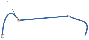
Corner Point –– converts a selected point into a corner point, as shown in Figure 39. Corner points have two movable control points, which are independent from each other, and allows a corner to be created in a curve.
Figure 39: Example of a corner point
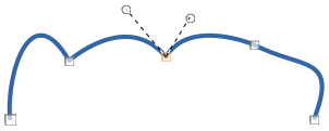
Smooth Transition –– converts a corner or symmetrical point into a smooth point, as shown in Figure 40. Both control points of a smooth transition point are aligned in parallel and can only be moved simultaneously. The control points may differ in length, allowing the degree of curvature to be varied.
Figure 40: Example of a smooth transition point
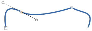
Symmetric Transition –– converts a corner point or a smooth point into a symmetrical point, as shown in Figure 41. Both control points of a symmetrical transition point are aligned in parallel and have the same length. These control points can only be moved simultaneously and the degree of curvature is the same in both directions.
Figure 41: Example of a symmetrical transition point
Eliminate Points – allows selection of several points before using the Delete Points tool. This is useful when deleting a straight line segment to create a complete curve.
Draw supports comments similar to those in Writer and Calc. For more about adding, navigating, and replying to comments, see the Getting Started Guide for more information. Comments in Draw cannot be printed. To reply to a comment in Draw, a new comment has to be added.
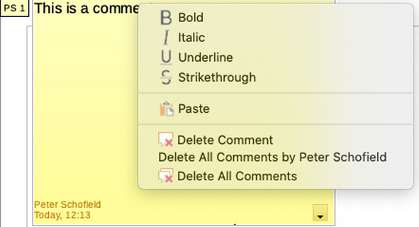
1) Go to Insert > Comment on the Menu bar and a comment box (Figure 42) appears in the upper left-hand corner of a drawing. Draw automatically adds the user name and date at the bottom of the comment and places a comment marker on the drawing page.
2) Type or paste a comment into the comment text box.
3) To apply basic formatting to the text, right-click on the text and select the formatting option from the context menu.
4) To delete a comment, use one of the following methods:
Right-click in the comment box and select a delete option from the context menu.
Right-click on the comment marker and select a delete option from the context menu.
Click on the triangle ▼ in the bottom right of the comment box and select a delete option from the context menu.
5) To move a comment, click on the comment marker and drag it to a new position.
6) To hide comments, use one of the following methods:
Go to View on the Menu bar and deselect Comments to hide the comment and the comment marker.
Click on the drawing outside of the comment to hide the comment. The comment marker remains visible.
7) To show comments, go to View > Comments on the Menu bar and click on the comment marker.
Figure 42: Comments in Draw
Note
For the user name and initials to appear in a comment, enter the user data in Tools > Options > LibreOffice > User Data dialog (macOS LibreOffice > Preferences > LibreOffice > User Data). If more than one person edits the document, each author is automatically allocated a different background color.
The x-axis is the horizontal position of an object and the y-axis is the vertical position of an object. The rulers do not show a minus sign if there are negative coordinates. However, the minus sign for negative coordinates is shown in the position field in the Status Bar and the Position and Size dialog.
The Workspace in Draw is larger than the drawing page. The area outside the drawing page is one page width right and left and a half page above and below the drawing page. The size of the drawing page is indicated by highlighted portions in the horizontal and vertical rulers.
Draw objects can be drawn partly or wholly outside the drawing page and these objects are saved with the drawing. However, when the drawing is printed or exported, any object or portion of an object not on the drawing page is not included. This allows the Workspace area around the drawing page to be used for drafts when creating objects.
The coordinates of objects and snap guides are shown relative to the origin. The default origin for coordinates (0.00/0.00 position) is the top-left corner of the drawing page without margins or the top left corner of the drawing page where the margins intersect. To change the default origin, click and drag the intersection of the rulers in the top left corner of the Workspace to the desired position. Guide lines appear as the intersection is dragged from its default origin to its new position. This origin setting is only for the current view and is not saved in the document.
The area inside the default origin is the area used for the grid when the option Snap to Grid and Display Grid are selected.
To reset the default origin back to its original setting at the top-left corner of the page, double‑click in the top-left corner on the Workspace where the horizontal and vertical rulers meet.
Draw internally uses integer values in 1/100 mm. Therefore, for example, it is not possible to get an exact position for 1/8 inch. Also, many dialog fields are restricted to two decimals.
To work with the maximum possible accuracy, go to Tools > Options > LibreOffice Draw > General (macOS LibreOffice > Preferences > LibreOffice Draw > General) and set the option Unit of measurement to Millimeter. The rulers will show metric units after this option has been selected, To use another measurement unit for the rulers, right-click on a ruler and select the measurement unit from the context menu. The horizontal and vertical rulers can have different measurement units.