Draw Guide 7.4
Chapter 1,
Introducing Draw
This document is Copyright © 2023 by the LibreOffice Documentation Team. Contributors are listed below. This document maybe distributed and/or modified under the terms of either the GNU General Public License (https://www.gnu.org/licenses/gpl.html), version 3 or later, or the Creative Commons Attribution License (https://creativecommons.org/licenses/by/4.0/), version 4.0 or later. All trademarks within this guide belong to their legitimate owners.
Contributors for this edition:
Peter Schofield
Contributors for previous editions:
Elzett Kotze
Jean Hollis Weber
John A Smith
John Cleland
Kees Kriek
Martin Fox
Peter Schofield
Rachel Kartch
Regina Henschel
Vipul Gupta
Please direct any comments or suggestions about this document to the Documentation Team mailing list: loguides@community.documentfoundation.org.
Note
Everything sent to a mailing list, including email addresses and any other personal information that is written in the message, is publicly archived and cannot be deleted.
Published January 2023. Based on LibreOffice 7.4 Community.
Other versions of LibreOffice may differ in appearance and functionality.
Some keystrokes and menu items are different on macOS from those used in Windows and Linux. Table 1 below gives some common substitutions for the instructions in this user guide. For a more detailed list, see the application help.
Table 1: Example of macOS keyboard shortcuts
|
Windows or Linux |
macOS equivalent |
Effect |
|
Tools > Options on Menu bar |
LibreOffice > Preferences on Menu bar |
Access to setup options |
|
Right-click |
Ctrl+click and/or right-click depending on computer setup |
Opens a context menu |
|
Ctrl or Control |
⌘ and/or Cmd or Command, depending on keyboard |
|
|
Alt |
⌥ and/or Alt or Option depending on keyboard |
Used with other keys |
LibreOffice Draw is a vector graphics drawing program, although it can also perform some operations on raster graphics (pixels). Using Draw, a wide variety of graphical images can easily and quickly be created.
Vector graphics store and display an image as an assembly of simple geometric elements such as lines, circles, and polygons, rather than a collection of pixels (points on the screen). Vector graphics allow for easier storage and scaling of the image.
Draw is fully integrated into the LibreOffice suite, and this simplifies exchanging graphics with all components of the LibreOffice suite. If an image is created in Draw, reusing it in a Writer document is relatively easy. For example, select and copy the drawing in Draw and then paste the image directly into a Writer document. Also, drawings can be worked on directly from within Writer or Impress, using a subset of the functions and tools from Draw.
The functionality of LibreOffice Draw is extensive. Draw was not designed to rival high-end graphics applications, but it possesses more functionality than the drawing tools that are generally integrated with the majority of office productivity suites. A few examples of the drawing functions are as follows:
This Draw Guide is not a course book to be worked through from beginning to end. Rather, it is a reference work in which can be browsed for guidance on particular topics.
This document describes only the functions associated with Draw. Some concepts, such as file management or the way the LibreOffice environment works, are mentioned only briefly and are covered in more detail in the Getting Started Guide.
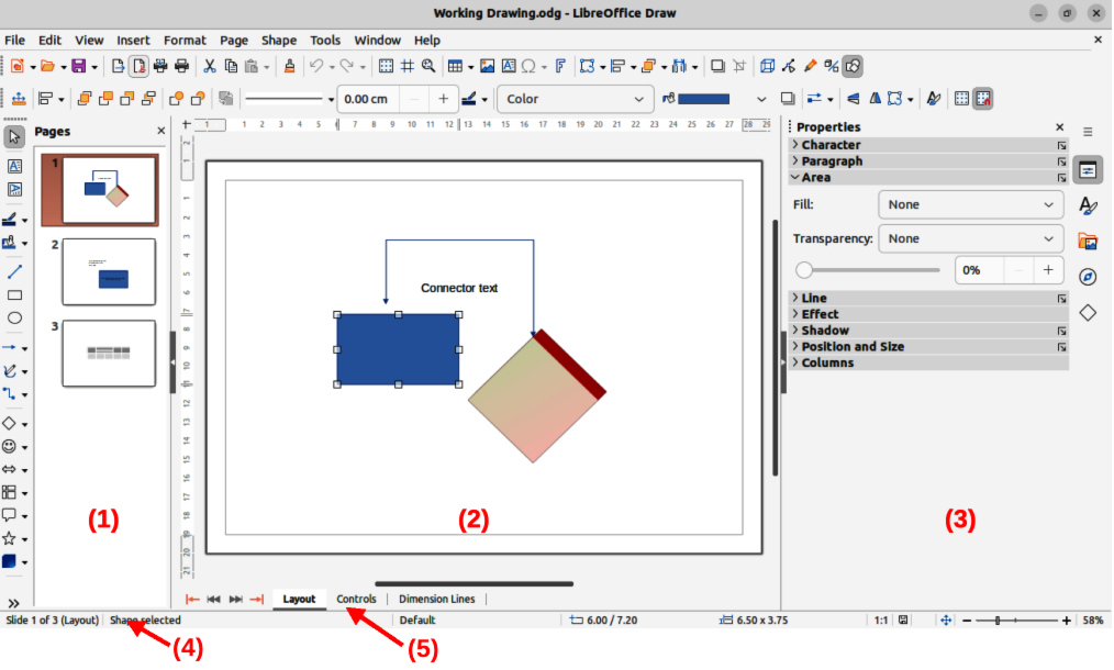
The large area in the center of the Draw main window (Figure 1) is the Workspace where drawings are created. This drawing area can be surrounded with toolbars and information areas. The number and position of the visible tools vary with the task being carried out, user preferences, and computer setup.
The maximum size of a drawing page in LibreOffice Draw is limited by the computer setup and the page size that that can be set and used in the printer connected to the computer.
In Draw, drawings can be split over several pages. Multi-page drawings are used mainly for presentations. The Pages pane, on the left side of the Draw main window, provides an overview of the pages that created in a drawing. If the Pages pane is not visible, go to View > Page Pane on the Menu bar. To make changes to the page order, drag and drop one or more pages displayed in the Pages pane.
A layer is a workplace where drawing elements and objects can be inserted. By default, the Workspace consists of three layers (Layout, Controls and Dimension Lines) and the tabs for these default layers appear at the bottom of the Workspace. The default layers cannot be deleted or renamed, but layers can be added as and when necessary.
Tabs for layers appear in the Layers bar at the bottom of the Workspace. The Layers bar allows for navigation between layers, adding layers as required, or deleting layers that have been created. For more information on layers, see Chapter 11, Advanced Draw Techniques.
The Sidebar in Draw has five main decks and is similar to the Sidebar in the other LibreOffice modules. To open a deck, click on its icon on the right of the Sidebar, or click on Sidebar Settings at the top of the Sidebar and select a deck from the drop-down list. If the Sidebar is not visible, go to View > Sidebar on the Menu bar, or use the keyboard shortcut Ctrl+F5 (macOS ⌘+F5).
Properties
Styles
Gallery
Navigator
Shapes
Rulers are positioned on the upper and left-hand sides of the Workspace. If the rulers are not visible, go to View > Rulers in the Menu bar, or use the keyboard shortcut Ctrl+Shift+R (macOS ⌘+Shift+R). The rulers show the size of a selected object on the page using double lines (highlighted in Figure 2). Also, rulers can be used to manage object handles and guide lines when positioning objects.
The page margins in the drawing area are also represented on the rulers. Change the margins directly on the rulers by dragging them with the cursor. The margin areas are normally indicated by a grayed out area on the rulers as shown in Figure 2, but this does depend on computer operating system and setup.
To change the measurement units of the rulers, right-click on a ruler and select the measurement unit from the drop down list, as shown in Figure 3 for the horizontal ruler. Measurement units for the horizontal and vertical rulers can be set to different measurement units.
Figure 2: Rulers showing object size
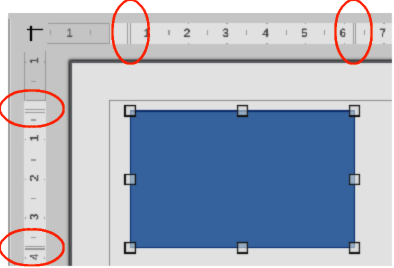
Figure 3: Ruler measurement units
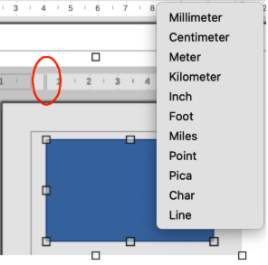
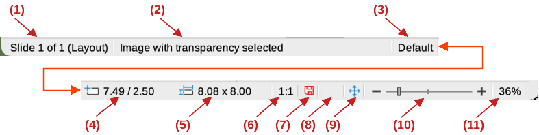
Figure 4: Status bar
Slide (drawing) number
Information area
Master drawing
Cursor position
Selected object size
Scaling factor of the document
Unsaved changes
Digital signature
Fit drawing
Zoom slider
Zoom percentage
The Status Bar (Figure 4) is located at the bottom of the Workspace in all LibreOffice modules. To hide the Status Bar, go to View on the Menu bar and deselect Status Bar.
Note
The measurement units shown on the Status Bar are set by going to Tools > Options > LibreOffice Draw > General (macOS LibreOffice > Preferences > LibreOffice > General) on the Menu bar. These measurement units can be different to the measurement units set for the rulers.
Slide (drawing) number
Information area
Master drawing
Cursor position/Selected object size
When no object is selected, the position numbers show the current position (X and Y coordinates) of the mouse cursor.
When an object is selected and being resized with the mouse, the object size numbers show the size of the object (width and height).
If an object is selected, the position numbers shows the X and Y coordinates of the upper-left corner and the object size number pair displays the size of the object. These numbers do not relate to the object itself, but to the selection outline, which is the smallest possible rectangle that can contain the visible part or parts of the object; see Chapter 3, Working with Objects and Object Points for more information.
When an object is selected, clicking in either of these areas opens the Position and Size dialog. See Chapter 4, Changing Object Attributes for more information.
Scaling factor of the document
Unsaved changes
Digital signature
Fit drawing
Zoom slider/Zoom percentage
To display or hide the various Draw toolbars, go to View > Toolbars on the Menu bar and select from the drop-down menu the toolbar required. For example, the Standard and Drawing toolbars are shown by default, but the Line and Filling, Text Formatting, and Options toolbars are not shown.
The appearance of the tool icons on toolbars depends on the computer operating system and the selection of icon style and size in Tools > Options > LibreOffice > View (macOS LibreOffice > Preferences > LibreOffice > View).
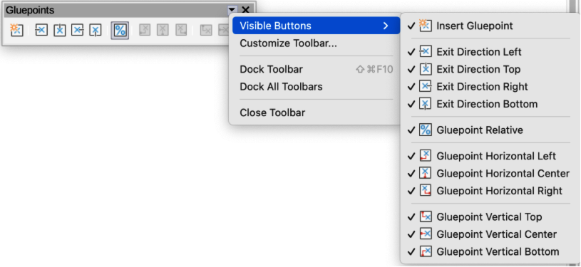
The tools available on a toolbar are indicated, either, by a shaded outline around the tool icon, or a check mark as shown by the example in Figure 5. For more information about working with toolbars, see Appendix B, Toolbars and the Getting Started Guide.
Figure 5: Example of Visible Buttons on a toolbar
The four main toolbars used in Draw are as follows:
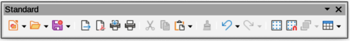
Standard toolbar
Figure 6: Standard toolbar
Drawing toolbar
Figure 7: Drawing toolbar
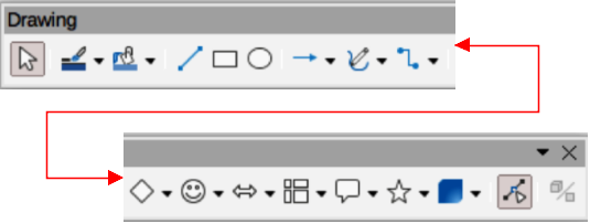
Figure 8: Line and Filling toolbar
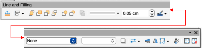
Line and Filling toolbar
Text Formatting toolbar
Figure 9: Text Formatting toolbar
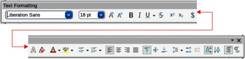
The default set of tools on each toolbar can be modified using Visible Buttons. Adding or removing a tool is as follows:
1) Either, right-click in an empty area on the toolbar, or click on the triangle ▼ in the toolbar title and select Visible Buttons from the context menu.
2) Click on a tool name in the sub-context menu that opens to add or remove the tool.
Note
For more information on the available tools that can be added to a toolbar, see Appendix B, Toolbars and the Getting Started Guide. When a tool is added to a toolbar, its position on the toolbar (from left to right) is the same as its position in the Visible Buttons context menu.
Figure 10: Available toolsets
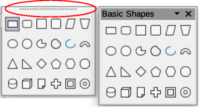
Some tools on a toolbar have a triangle ▼ to the right side of the tool icon indicating that the tool has additional tools available in a sub-toolbar. Clicking on this triangle ▼ displays the full set of available tools (Figure 10).
This palette or sub-toolbar can be turned into a floating toolbar. Click the area at the top of the toolset highlighted in Figure 10, drag it across the screen to a convenient location and release the cursor. To close a floating toolbar, click on the X on the right of the toolbar title.
Note
When a sub-toolbar is made into a floating toolbar, the tool on the existing toolbar remains in the toolbar and always shows the last tool used. This means that the tool icon on a screen may differ from the tool icon shown in this guide.
Tip
When double-clicking on a tool, the command corresponding to that tool becomes active and remains active. The tool command can be repeated as often as required. To exit from this mode, press the Esc key or click on another tool. Please note that this may not work for every tool on every toolbar.
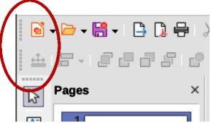
By default when Draw is opened, any docked toolbars are locked into position and have to be unlocked before becoming floating toolbars or repositioned on the Draw main window. The locking status of toolbars is indicated by dotted handles at the left end of horizontal toolbars, as shown highlighted in Figure 11. For vertically positioned toolbars, these dotted handles are positioned at the top of the toolbar.
Notes
Make sure that all toolbars are docked into the required position in the LibreOffice window before using Lock Toolbars or Lock Toolbar Position.
No dotted handles on toolbars indicates that the toolbars are locked and the following procedures have to be used to unlock toolbars.
Figure 11: Toolbar handles
All toolbars available in LibreOffice can be locked into position. This overrides any unlocking of individual toolbars. To unlock or lock all the toolbars, use the following procedure:
1) Make sure all open LibreOffice documents have been saved.
2) To unlock all toolbars, go to View > Toolbars on the Menu bar and select Lock Toolbars from the context menu.
3) Select Restart Now from the warning message that opens and all toolbars can now be individually unlocked. Toolbar handles now appear on individual toolbars that are not locked.
4) To lock all toolbars, go to View > Toolbars on the Menu bar and select Lock Toolbars from the context menu.
5) Select Restart Now from the warning message that opens and all toolbars are now locked into position. Toolbar handles are no longer displayed.
Individual toolbars can be unlocked or locked using the following procedure:
1) To unlock a toolbar, right-click in a blank area on the toolbar and select Lock Toolbar Position from the context menu. A toolbar handle appears at the end of the toolbar, indicating that the toolbar is unlocked and can be moved.
2) To lock a toolbar into position, dock the toolbar into position, then right-click in a blank area on the toolbar and select Lock Toolbar Position from the context menu. The toolbar handle disappears from the end of the toolbar.
Note
There is no selection indication on Lock Toolbars, or Lock Toolbar Position in the context menus. The locking indication is only indicated by the toolbar handles.
When Draw is opened, the Standard and Drawing toolbars, by default, are already docked into their positions on the main Draw window. These toolbars can be undocked creating floating toolbars as follows:
1) Make sure the toolbar handle is displayed indicating that the toolbar is unlocked. If there is no toolbar handle displayed, see “Unlocking and locking toolbars” on page 1 for more information.
2) Move the cursor to the far left of the toolbar and over the toolbar handle. The cursor changes shape, normally to a grabbing hand, depending on computer setup and operating system.
3) Click and drag on the toolbar handle and move the toolbar until it is undocked and becomes a floating toolbar. This floating toolbar capability is common to all components of LibreOffice.
To dock a floating toolbar use one of the following methods:
Press and hold the Ctrl key (macOS ⌘), then double click on the title of the toolbar. The toolbar moves into available space at the top of the Draw main window.
Click in the toolbar title and drag the toolbar to the docked position required. This can be the top, bottom or one of the sides of the Draw main window.
Draw toolbars can be customized by adding or removing commands to or from a toolbar. Also, customization allows the creation of toolbars for specific purposes. Customizing toolbars is in addition to using “Adding and removing tools” on page 1. For more information on adding new commands, modifying toolbars, or creating toolbars, see Appendix B, Toolbars and the Getting Started Guide.
The Color Palette (Figure 12) provides quick access to a standard set of colors to use for selected objects and text in a drawing.
1) Go to View on the Menu bar and select Color Bar to open the Color Palette.
2) Select an object or text.
3) Left click on the color required for the area fill or text and change the color of the object or text.
4) Right click on the color required for the object or text box border and change the color of the border.
5) Go to View on the Menu bar and deselect Color Bar to close the Color Palette.
Figure 12: Color Palette (Color Bar)
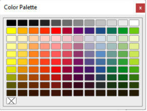
Note
The box with the X at the bottom left of the Color Palette corresponds to none (no color).
In addition to the standard Color Palette, Draw has several specialized color palettes available, giving a greater choice of color: for example, chart-palettes, material, html, and so on. After selecting an object or text in a drawing, use one of the following to access the specialized color palettes.
Area or fill color — Color page in the Area dialog, Fill Color on the Drawing or Line and Filling toolbar, or Fill in the Area section in the Properties deck on the Sidebar.
Line color — Line page in the Line dialog, Line Color on the Drawing or Line and Filling toolbar, or Color in the Line section in the Properties deck on the Sidebar.
Text color — Font Color tool on the Text Formatting toolbar, or Font Color in the Character section in the Properties deck on the Sidebar.
For more information on selecting a color and a color palette for an object or text, see Chapter 4, Changing Object Attributes, Chapter 9, Adding and Formatting Text and Chapter 11, Advanced Draw Techniques.
In Draw, custom colors can be created using the Color Picker dialog, CMYK values, or RGB values to match specific color schemes used, for example, by a company. For more detailed information on creating custom colors and color palettes, as well as more information on CMYK and RGB color schemes, refer to Chapter 11, Advanced Draw Techniques.
The grid, snap guides, and helplines in Draw act as drawing aids when moving and positioning objects in a drawing. These drawing aids can be turned on or off as follows:
Line and Filling toolbar — click on Display Grid or Helplines While Moving to turn the grid or helplines on or off.
Options toolbar — click on Display Grid, Display Snap Guides, or Helplines While Moving to turn the grid, snap guides, or helplines on or off.
Go to View > Grid and Helplines on the Menu bar and select or deselect Display Grid or Helplines While Moving on the submenu.
Go to View > Snap Guides on the Menu bar and select or deselect Display Snap Guides on the submenu.
The grid and snap guides are displayed only on the screen and are not shown on a printed drawing or when the drawing is used in another LibreOffice module. The color, spacing and resolution of the grid points can be individually chosen for each axis. Draw also offers several snap functions to position objects exactly in a drawing.
Helplines show the position of the object while moving and makes positioning an object much easier. If this function is activated, pairs of vertical and horizontal lines enclosing the object are shown while moving the object. These helplines extend to the edges of the drawing area.
For more information on the grid, snap guides, snap functions, and helplines, see Chapter 3, Working with Objects and Object Points.