Copyright
This document is Copyright © 2026 by the LibreOffice Documentation Team. Contributors are listed below. This document may be distributed and/or modified under the terms of either the GNU General Public License (https://www.gnu.org/licenses/gpl.html), version 3 or later, or the Creative Commons Attribution License (https://creativecommons.org/licenses/by/4.0/), version 4.0 or later. All trademarks within this guide belong to their legitimate owners.
Contributors
To this edition
Peter Schofield
To previous editions
Peter Schofield
Feedback
Please direct any comments or suggestions about this document to the Documentation Team Forum at https://community.documentfoundation.org/c/documentation/loguides/ (registration is required) or send an email to: loguides@community.documentfoundation.org.
-
Note
Everything sent to a forum, including email addresses and any other personal information that is written in the message, is publicly archived and cannot be deleted. Emails sent to the forum are moderated.
Publication date and software version
Published August 2026. Based on LibreOffice 26.2 Community.
Introduction
In Impress several toolbars are available for creating a presentation. Each toolbar has a default set of tools and an option to add additional tools to a toolbar.
-
Notes
The icons displayed on the Impress toolbars illustrated in this appendix may differ from what is displayed on a computer screen. Toolbar icons depend on the computer operating system being used and how LibreOffice has been configured. For more information on customizing LibreOffice and toolbars, see the Getting Started Guide.
Some toolbars when selected do not display until an object of the correct type is selected in a presentation. For example, the Image toolbar only displays when an image, or graphic, using an image file format is selected.
Using toolbars
Displaying toolbars
Two methods of opening toolbars in Impress are used, as follows:
-
Go to View > Toolbars on the Menu bar. A submenu opens with an alphabetical list of toolbars available for creating presentations in Impress.
-
Click on a toolbar name to display it and make it active. Active toolbars are indicated by highlighting or a check mark next to the toolbar name, depending on computer setup.
-
Note
When selecting tools on a toolbar, a subtoolbar may open providing more tools to edit an object. For example, clicking on Color in the Image toolbar opens the Color subtoolbar to adjust the color settings of an image.
Closing toolbars
To close a toolbar, use one of the following methods:
-
Go to View > Toolbars on the Menu bar and deselect the toolbar.
-
Right-click in a blank area on a toolbar and select Close Toolbar from the context menu.
-
Click on the X in the right corner of the title bar of a floating toolbar.
Moving toolbars
Docked toolbars
By default, some toolbars are docked into position in the Impress main window. For example, the Standard toolbar is docked at the top of the main window. Docked toolbars can be undocked and moved to a new docked position on the main window, or left as a floating toolbar.
-
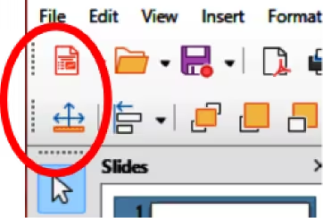
Move the cursor over the small vertical handle at the left end or top of the toolbar (highlighted in Figure 1). The cursor changes shape to the moving cursor used for the computer system and setup.
-
Click and drag the toolbar to a new location. This can be a new docked position, or a floating toolbar. A hashed border appears around the toolbar indicating the toolbar position as it is dragged.
-
Release the cursor when the required position is reached.
Figure 1: Toolbar moving handles
-
Note
If the toolbar moving handles are not visible at the left end or top of a docked toolbar, then the toolbar is locked into position. A docked toolbar must be unlocked before it can be moved to a new position in the Impress main window. See “Locking and unlocking toolbars” below for more information.
Floating toolbars
-
To move a floating toolbar, click on its title bar and drag it to a new floating location.
-
Release the toolbar when it is in the required position.
-
Note
Floating toolbars does not have to be placed on the Impress main window to function.
Floating Subtoolbars
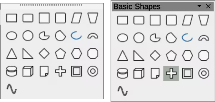
Some tools on a toolbar have a triangle ▼ to the right of the tool indicating that more tools are available on a subtoolbar, for example Basic Shapes on the Drawing toolbar. Subtoolbars can be turned into floating Subtoolbars and moved into a new position as follows:
-
Move the cursor over the horizontal handle at the top of the subtoolbar (Figure 2). The cursor changes to the moving cursor used for the computer system and setup.
-
Click and drag the subtoolbar to a new location to create a floating subtoolbar.
-
Release the subtoolbar when it is in the required position is reached.
-
To close the floating subtoolbar use one of the following methods:
-
Right-click on the triangle ▼ in the subtoolbar title bar and select Close Toolbar from the context menu.
-
Click on the X at the right end of the subtoolbar title bar.
Docking toolbars
To dock a floating toolbar, use one of the following methods:
-
Click on the title bar and drag it to a docking position on the main window. When a toolbar reaches a docking position, a hashed border appears at the docked position. Release the toolbar and it is docked into position.
-
Right-click on the toolbar and select Dock Toolbar from the context menu. The toolbar moves into a docked position. If the position is not suitable, move the toolbar to a new docked position.
Figure 2: Creating floating toolbars
-
To dock all floating toolbars that are active, right-click on the toolbar and select Dock All Toolbars from the context menu.
Locking and unlocking toolbars
Docked toolbars
When a toolbar has been docked into position on the Impress main window, the toolbar can be locked into position preventing the toolbar from becoming a floating toolbar.
-
To lock a toolbar into a docked position, right-click in a blank area on the toolbar and select Lock Toolbar Position from the context menu. A check mark appears against this option indicating the toolbar is now locked. The small vertical or horizontal bar disappears from the top or left end of the toolbar indicating that the toolbar is locked.
-
To unlock a toolbar, right-click in a blank area on the toolbar and click on Lock Toolbar Position in the context menu. The check mark next to this option disappears indicating the toolbar is now unlocked. A small vertical or horizontal bar appears at the top or left end of a toolbar indicating that the toolbar is unlocked. This bar is also is used to move a toolbar.
-
Notes
Some toolbars cannot be docked or locked into position. This is indicated by the options Dock Toolbar and/or Lock Toolbar Position being grayed out, making the options unavailable.
Using the Lock Toolbars option affects ALL toolbars and Subtoolbars available in all LibreOffice modules.
Locking and unlocking toolbars and Subtoolbars
To prevent toolbars and Subtoolbars from becoming floating toolbars or Subtoolbars, they can be locked. Also, locked toolbars and Subtoolbars can be unlocked using the same method below. The Lock Toolbars option is a lock/unlock switch.
-
Save the presentation that is open in Impress, then go to View > Toolbars on the Menu bar and select Lock Toolbars from the submenu.
-
Select Restart Now in the Restart LibreOffice dialog that opens to activate the Lock Toolbars option.
-
To unlock toolbars or Subtoolbars to create floating toolbars or Subtoolbars, repeat Steps 1 and 2.
Editing toolbars
When LibreOffice is installed on a computer, a set of toolbars suitable for each LibreOffice component is also installed. Each toolbar has a default set of visible tools. Tools can be added or deleted, and toolbars can be customized.
Adding tools
-
Right-click in a blank area on a toolbar, or click on the triangle ▼ on the right of the toolbar title bar.
-
Select Visible Buttons from the context menu to display a list of available tools.
-
Click on the tool required and the tool appears in the toolbar. The list of available tools closes automatically. If there is a highlight or check mark next to the tool, then that tool is already installed on the toolbar.
-
Note
When adding tools using Visible Buttons, the tool is added to the toolbar in the same position as the tool appears in the Visible Buttons list. That is, the top tool in the Visible Buttons list appears at the left end or top of the toolbar and the bottom tool appears at the right end or bottom of the toolbar. Tool positions on a toolbar cannot be changed.
Deleting tools
-
Right-click in a blank area on a toolbar, or click on the triangle ▼ on the right of the toolbar title bar.
-
Select Visible Buttons from the context menu to display a list of available tools.
-
Click on the tool no longer required and the tool is removed from the toolbar. The highlight or check mark next to the tool is also removed. The list of available tools closes automatically.
Customizing toolbars
Extra tools and commands that are not available in Visible Buttons can be added to a toolbar using customization. Customization also allows the creation of new toolbars if a specific set of tools are required for a specific task. For information on customizing toolbars, see the Getting Started Guide.
Toolbars
-
The number of tools visible on a toolbar depend on the computer setup that is being used to create a presentation.
-
The tools displayed on the toolbars in this chapter are EXAMPLES only.
-
The tools already installed on a toolbar are indicated in Visible Buttons either by the tool icon being highlighted or by a check mark. This install indication depends on computer setup and computer operating system being used.
-
On some toolbars, tool icons may have a triangle ▼ to the right of the icon. Click on this triangle to open a list of options, or subtoolbar.
-
Some tools also have the option of using a keyboard shortcut instead of clicking on the tool. Keyboard shortcuts are displayed on the right of the tool icon. For a full list of keyboard shortcuts that are available in Impress, see Appendix A, Keyboard Shortcuts.
-
The numbered legend for the available tools in a toolbar indicate the position of the tool in a toolbar. For example, (1) indicates that the tool is positioned at the left end of the toolbar.
3D-Objects
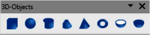
The 3D-Objects toolbar (Figure 3) provides for creating 3D objects in a slide. Go to View > Toolbars > 3D-Objects on the Menu bar. Alternatively, click on the triangle ▼ next to 3D‑Objects on the Drawing toolbar to open a subtoolbar for access to the same 3D tools.
Figure 3: 3D-Objects toolbar
-
Cube
-
Sphere
-
Cylinder
-
Cone
-
Pyramid
-
Torus
-
Shell
-
Half Sphere
3D-Settings
The 3D-Settings toolbar (Figure 4) and these tools are only active when an object has been converted to 3D using the tool Toggle Extrusion and the converted object is selected.
Figure 4: 3D-Settings toolbar

-
Toggle Extrusion
-
Tilt Down
-
Tilt Up
-
Tilt Left
-
Tilt Right
-
Depth
-
Direction
-
Lighting
-
Surface
-
3D Color
For the following tools on the 3D-Settings toolbar click on the triangle ▼ on the right of the icon for access to various options as follows:
Depth
Direction
Lighting
Surface
3D Color
Align Objects
The Align Objects toolbar (Figure 5) provides tools for aligning several objects in a slide to improve the visual impact of objects on a slide.
Figure 5: Align Objects toolbar
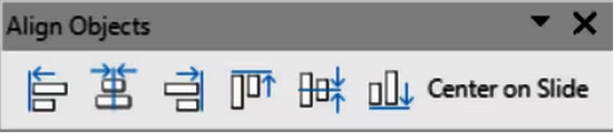
The tools available on the Align Objects toolbar provide the following options:
Left
Centered
Right
Top
Center
Bottom
Center on Slide
Comments
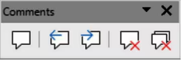
The Comments toolbar (Figure 6) provides tools for adding, deletion, and navigation of comments in a presentation. When adding comments to a presentation, it is recommended a user to add their name and initials in Tools > Options > LibreOffice > User Data (macOS LibreOffice > Preferences > LibreOffice > User Data).
Figure 6: Comments toolbar
-
Comment
-
Previous Comment
-
Next Comment
-
Delete Comment
-
Delete All Comments
Distribute Selection
The Distribute Selection toolbar (Figure 7) is used to distribute three or more objects evenly along the horizontal or vertical axis. Also, the spacing between objects can be evenly distributed.
Figure 7: Distribute Selection toolbar
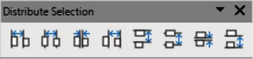
The tools available on the Distribute Selection toolbar provide the following options:
Distribute Horizontally Left
Distribute Horizontally Center
Distribute Horizontally Spacing
Distribute Horizontally Right
Distribute Vertically Top
Distribute Vertically Center
Distribute Vertically Spacing
Distribute Vertically Bottom
Drawing
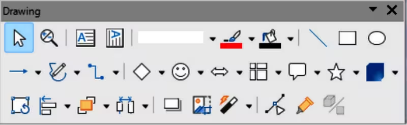
The Drawing toolbar (Figure 8) provides the tools used to create graphic objects on slides in a presentation. By default, this toolbar is docked on the left side of the Workspace.
Figure 8: Drawing toolbar
-
Select
-
Zoom & Pan
-
Zoom
-
Text Box
-
Vertical Text
-
Insert Fontwork
-
Line Style
-
Line Color
-
Fill Color
-
Line
-
Rectangle
-
Ellipse
-
Line Ends with Arrow
-
Lines and Arrows
-
Curves and Polygons
-
Connectors
-
Basic Shapes
-
Symbol Shapes
-
Arrow Shapes
-
Flowchart Shapes
-
Callouts Shapes
-
Star Shapes
-
3D Objects
-
Position and Size
-
Rotate
-
Flip
-
Align Objects
-
Arrange
-
Distribution
-
Shadow
-
Crop Image
-
Filter
-
Toggle Edit Point Mode
-
Gluepoints
-
To Curve
-
To Polygon
-
To 3D
-
T0 3D Rotation Object
-
Toggle Extrusion
-
Insert
-
Controls
Some tool shapes on the Drawing toolbar change indicating the tool has been previously used.
-
Where available, click on the triangle ▼ to the right of a tool icon to open a pop-up toolbar, then select the required shape to add to a drawing. For more information on Subtoolbars, see “Subtoolbars” below.
-
To create a floating subtoolbar, click on the handle (Figure 2) at the top of the pop-up toolbar and drag to an empty area on the main window.
Edit Points
The Edit Points toolbar (Figure 9) provides tools for editing the points of a curve or polygon, or an object that has been converted to a curve or polygon. The toolbar only becomes active when an object is selected. Click on Edit Points on the Drawing or Standard toolbar, or use the keyboard shortcut F8 to open the toolbar.
Figure 9: Edit Points toolbar

-
Move Points
-
Insert Points
-
Delete Points
-
Convert to Curve
-
Close Bezier
-
Split Curve
-
Corner Point
-
Smooth Transition
-
Symmetric Transition
-
Eliminate Points
Find
The Find toolbar (Figure 10) opens by default and is docked in the bottom left corner of the Impress main window above the Status bar. This toolbar can be undocked from its default position and made into a floating toolbar.
Figure 10: Find toolbar

-
Close Find Bar
-
Find Values
-
Find Previous
-
Find Next
-
Find All
-
Match Case
-
Match Diacritics
-
Find and Replace
-
Search Results Message
Fontwork
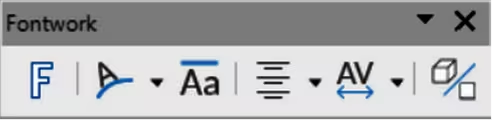
The Fontwork toolbar (Figure 11) is used to create graphical text objects in a slide and provide the tools for editing a graphical text object. This toolbar only becomes active when a Fontwork graphical text object has been selected on a slide.
Figure 11: Fontwork toolbar
-
Insert Fontwork
-
Fontwork Shape
-
Fontwork Same Letter Heights
-
Fontwork Alignment
-
Fontwork Character Spacing
-
Toggle Extrusion
Some tools on the Fontwork toolbar have a triangle ▼ to the right of the tool. Click on this triangle to open a pop-up toolbar, or drop-down option list.
Fontwork Shape
Fontwork Alignment
Fontwork Character Spacing
Gluepoints
The Gluepoints toolbar (Figure 12) provides tools to insert a gluepoint or modify the properties of a gluepoint. A gluepoint is where a connector is attached or glued to an object.
Figure 12: Gluepoints toolbar

-
Insert Gluepoint
-
Exit Direction Left
-
Exit Direction Top
-
Exit Direction Right
-
Exit Direction Bottom
-
Gluepoint Relative
-
Gluepoint Horizontal Left
-
Gluepoint Horizontal Center
-
Gluepoint Horizontal Right
-
Gluepoint Vertical Top
-
Gluepoint Vertical Center
-
Gluepoint Vertical Bottom
Image
The Image toolbar (Figure 13) provides tools to edit, modify, align, reposition and resize images. The toolbar only becomes active and available when an image is selected in a presentation. The Image toolbar automatically replaces the Line and Filling toolbar when it becomes active.
Figure 13: Image toolbar
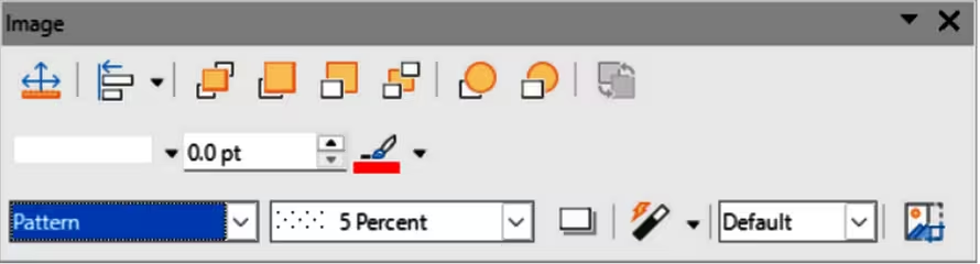
-
Position and Size
-
Align Objects
-
Left
-
Centered
-
Right
-
Top
-
Middle
-
Bottom
-
Center on Slide
-
Arrange
-
Bring to Front
-
Forward One
-
Backward One
-
Send to Back
-
In Front of Object
-
Behind Object
-
Reverse
-
Line Style
-
Line Thickness
-
Line Color
-
Area Style/Filling
-
Fill Color
-
Shadow
-
Filter
-
Image Mode
-
Crop
-
Vertically
-
Horizontally
-
Transformations
-
Transparency
-
Color
-
Line
-
Area
-
Animation
-
Interaction
Insert
The Insert toolbar (Figure 14) provides tools to insert different types of objects into a slide.
Figure 14: Insert toolbar
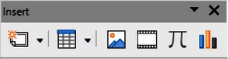
-
New Page
-
Insert Page from File
-
Table
-
Image
-
Media
-
Formula Object
-
Chart
-
Insert OLE Object
Legacy Circles and Ovals
The Legacy Circles and Ovals toolbar (Figure 15) provides tools to insert different types of circles and ovals into a drawing.
Figure 15: Legacy Circles and Ovals toolbar

-
Ellipse
-
Circle
-
Ellipse Pie
-
Circle Pie
-
Ellipse Segment
-
Circle Segment
-
Ellipse, Unfilled
-
Circle, Unfilled
-
Ellipse Pie, Unfilled
-
Circle Pie, Unfilled
-
Ellipse Segment, Unfilled
-
Circle Segment, Unfilled
-
Arc
-
Circle Arc
Legacy Rectangles
The Legacy Rectangles toolbar (Figure 16) provides tools to insert different types of rectangles and squares into a slide.
Figure 16: Legacy Rectangles toolbar
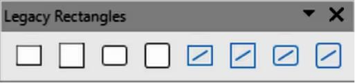
-
Rectangle
-
Square
-
Rectangle, Rounded
-
Rounded Square
-
Rectangle, Unfilled
-
Square, Unfilled
-
Rounded Rectangle, Unfilled
-
Rounded Square, Unfilled
Line and Filling
The Line and Filling toolbar (Figure 17) provides tools and drop-down lists for editing lines, arrows, and object borders. Tool availability depends on the type of object selected for editing.
Figure 17: Line and Filling toolbar
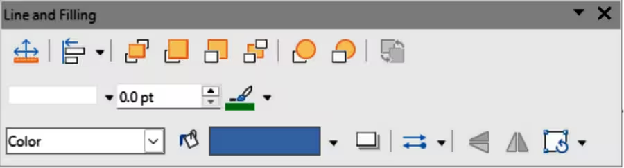
-
Position and Size
-
Align Objects
-
Left
-
Centered
-
Right
-
Top
-
Center
-
Bottom
-
Center on Slide
-
Arrange
-
Bring to Front
-
Forward One
-
Backward One
-
Send to Back
-
In Front of Object
-
Behind Object
-
Reverse
-
Line Style
-
Line Thickness
-
Line Color
-
Area Style/Filling
-
Fill Color
-
Shadow
-
Arrow Style
-
Vertically
-
Horizontally
-
Transformations
-
Line
-
Area
-
3D Effects
-
Image Map
-
Animation
-
Interaction
-
Styles
-
Grid
-
Snap to Grid
-
Helplines While Moving
Master View
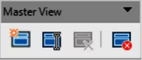
The Master View toolbar (Figure 18) provides tools to create a new master slide, rename a master slide, delete a master slide, and close master view. This toolbar is only active when Impress is in master view.
Figure 18: Master View toolbar
-
New Master
-
Rename Master
-
Delete Master
-
Close Master View
Media Playback
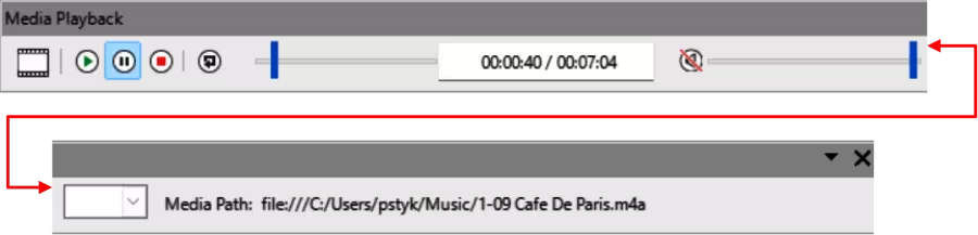
The Media Playback toolbar (Figure 19) provides the tools required to insert, view, play, and listen to audio and video files. The toolbar only becomes active when an audio or video file is selected. Impress supports many different media formats depending on the computer operating system being used.
Figure 19: Media Playback toolbar
-
Insert Audio or Video
-
Play
-
Pause
-
Stop
-
Repeat
-
Position
-
Mute
-
Volume
-
View
Options
The Options toolbar (Figure 20) provides tools for editing various settings for newly created presentations, for example how objects snap to the grid when being moved or resized.
Figure 20: Options toolbar

-
Rotation Mode After Clicking Object
-
Grid
-
Display Snap Guides
-
Helplines While Moving
-
Snap to Grid
-
Snap to Snap Guides
-
Snap to Page Margins
-
Snap to Object Borders
-
Snap to Object Points
-
Allow Quick Editing
-
Select Text Area Only
-
Double-click to edit Text
-
Modify Object with Attributes
-
Exit All Groups
Outline
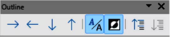
The Outline toolbar (Figure 21) provides tools for working with outlines.
Figure 21: Outline toolbar
-
Demote
-
Promote
-
Move Down
-
Move Up
-
Show Formatting
-
Black & White View
-
Show Only First Level
-
Show All Levels
-
Hide Subpoints
-
Show Subpoints
Presentation
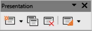
The Presentation toolbar (Figure 22) provides tools for working with presentations.
Figure 22: Presentation toolbar
-
New Slide
-
Du[plicate Slide
-
Rename Slide
-
Delete Slide
-
Slide Layout
-
Change Slide Master
-
Expand Slide
-
Go to First Slide
-
Go to Previous Slide
-
Go to Next Slide
-
Go to Last Slide
-
Move Slide to Start
-
Move Slide Down
-
Move Slide to End
Redaction
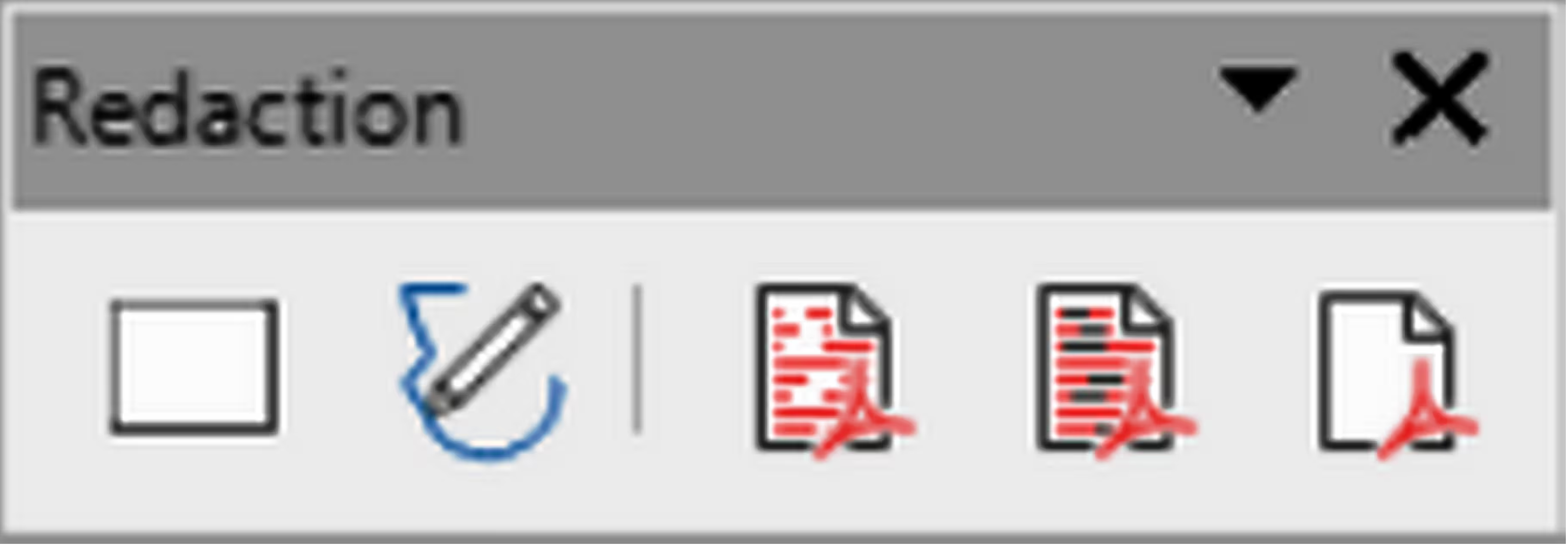
The Redaction toolbar (Figure 23) is used to block portions of a drawing when protecting sensitive information. Redaction helps enterprises and organizations to comply with regulations on confidentiality or privacy. When a redacted drawing is exported, any redacted portions are removed from the drawing and replaced by redaction blocks of pixels. This prevents any attempt in restoring or copying the original contents. A redacted drawing is often exported as PDF for publication or sharing.
Figure 23: Redaction toolbar
-
Rectangle
-
Freeform
-
Redacted Export (White)
-
Redacted Export (Black)
-
PDF
Slide View
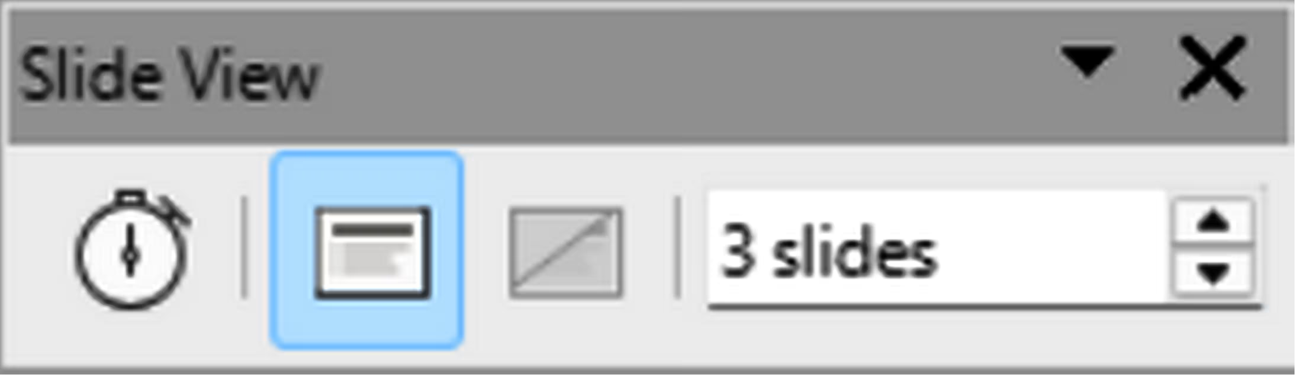
The Slide View toolbar (Figure 24) opens with the Slide Sorter view and provides tools to rehearse timings of a slide show; hide and show slides, and change the number of slides displayed in Slide Sorter view.
Figure 24: Slide View toolbar
-
Rehearse Timings
-
Show Slide
-
Hide Slide
-
Slides per Row
Standard
The Standard toolbar (Figure 25) is common to all LibreOffice modules and provides tools for creating and editing documents using LibreOffice. The Standard toolbar differs between different LibreOffice modules allowing different tool sets used in creating the different types of documents.
Figure 25: Standard toolbar

-
Load URL
-
New
-
Templates
-
Open
-
Open Remote
-
Save
-
Save As
-
Email
-
Edit Mode
-
Export Directly as PDF
-
Print Directly
-
Print
-
Cut
-
Copy
-
Paste
-
Clone
-
Clear
-
Undo
-
Redo
-
Find and Replace
-
Spelling
-
Auto Spellcheck
-
Zoom & Pan
-
Zoom
-
Grid
-
Snap to Grid
-
Helplines While Moving
-
Display Views
-
Views Tab Bar
-
Format Slide
-
Master Slide
-
Start from First Slide
-
Start from Current Slide
-
Table
-
Image
-
Media
-
Chart
-
Text Box
-
Symbol
-
Vertical Text
-
Insert Fontwork
-
Hyperlink
-
Draw Functions
-
Interaction
-
LibreOffice Help
-
What’s This?
Standard (Single Mode)
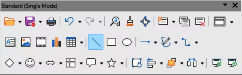
The Standard (Single Mode) toolbar (Figure 27) can be used instead of the Standard toolbar if necessary. The Standard (Single Mode) toolbar is normally used when the user interface is switched to single mode. For more information on selecting and using user interface variants, see Chapter 12, User Interface Variants.
Figure 26: Standard (Single Mode) toolbar
-
New
-
Open
-
Save
-
Export Directly as PDF
-
Print
-
Print Preview in Web Browser
-
Undo
-
Redo
-
Find and Replace
-
Clone Formatting
-
Spelling
-
Entire Page
-
New Slide
-
Duplicate Slide
-
Rename Slide
-
Delete Slide
-
Slide Layout
-
Display Views
-
Text Box
-
Vertical Text
-
Image
-
Media
-
Insert Chart
-
Table
-
Insert Fontwork
-
Line
-
Rectangle
-
Ellipse
-
Lines and Arrows
-
Curves and Polygons
-
Connectors
-
Basic Shapes
-
Symbol Shapes
-
Block Arrows
-
Flowchart
-
Callouts
-
Stars and Banners
-
3D Objects
-
Position and Size
-
Rotate
-
Flip
-
Align Objects
-
Arrange
-
Distribution
-
Group
-
Ungroup
-
Enter Group
-
Exit Group
-
Select
-
Entire Page
-
Zoom & Pan
-
Zoom
-
Start from First Slide
-
Start from Current Slide
Standard (Viewing Mode)
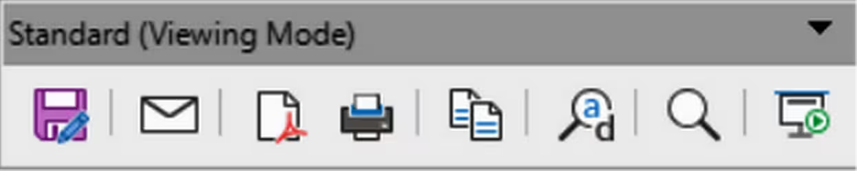
The Standard (Viewing Mode) toolbar (Figure 27) provides tools to save, edit and distribute a document.
Figure 27: Standard (Viewing Mode) toolbar
-
Save As
-
Edit Mode
-
Read Only Mode
-
Email
-
Export Directly as PDF
-
EPUB
-
Print Directly
-
Print
-
Copy
-
Find and Replace
-
Zoom
-
Start from First Slide
Table
The Table toolbar (Figure 28) provides tools and options to edit and format a table placed on a slide. This toolbar only becomes active when a table is selected.
Figure 28: Table toolbar

-
Table
-
Border Style
-
Border Color
-
Borders (Shift to overwrite)
-
Area Style/Filling
-
Fill Color
-
Merge Cells
-
Split Cells
-
Optimize
-
Top
-
Vertically
-
Bottom
-
Insert Row Above
-
Insert Row Below
-
Insert Column Before
-
Insert Column After
-
Delete Row
-
Delete Column
-
Delete Table
-
Select Table
-
Select Column
-
Select Row
-
Table Properties
Text
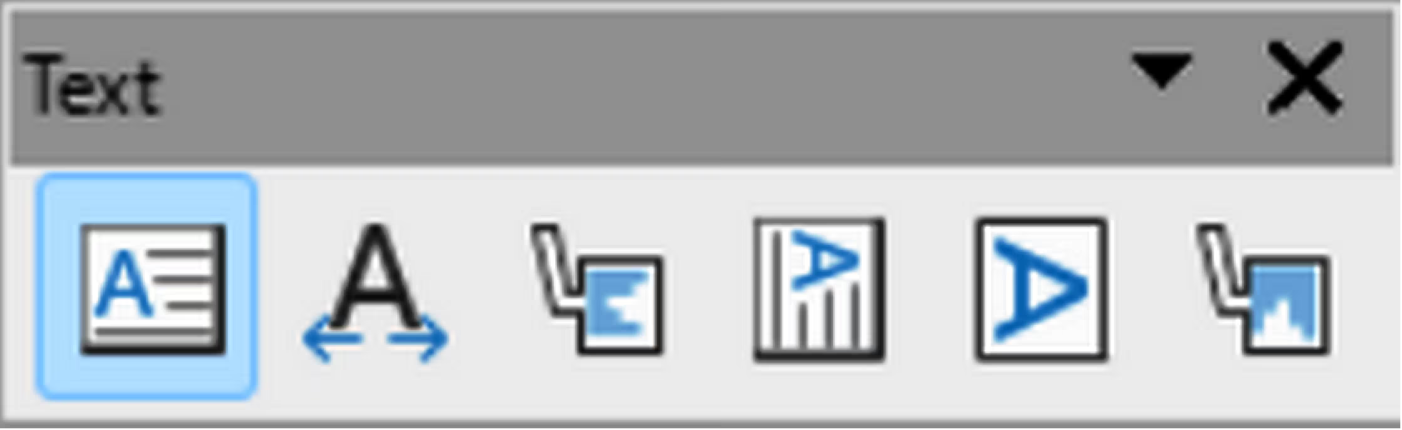
The Text toolbar (Figure 29) provides tools to insert text boxes and callouts into a slide.
Figure 29: Text toolbar
-
Insert Text Box
-
Fit Text in Text Box Size
-
Callouts
-
Vertical Text
-
Fit Vertical Text to Frame
-
Vertical Callouts
Text Formatting
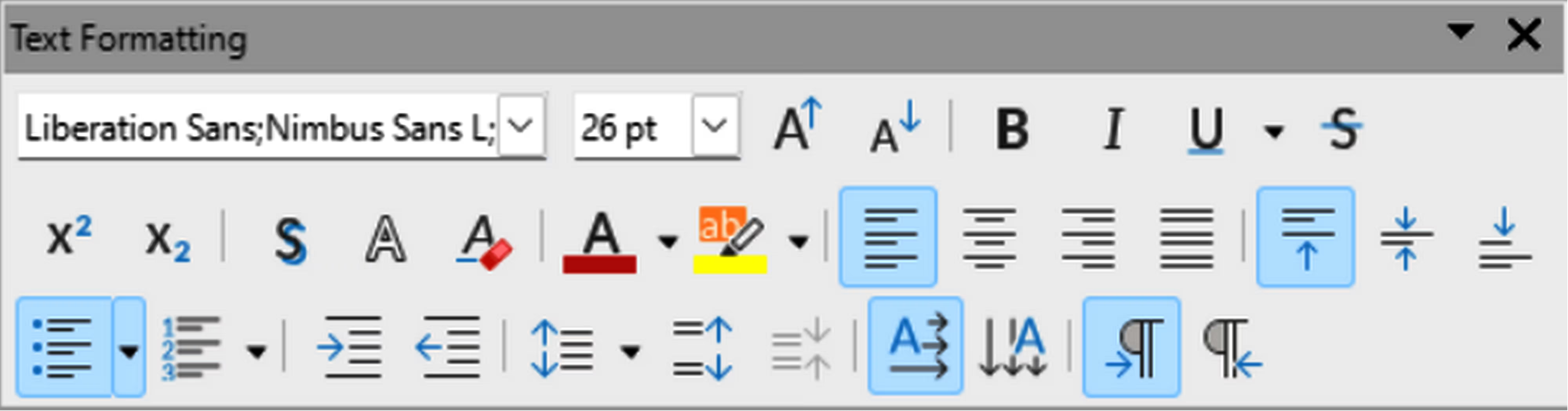
The Text Formatting toolbar (Figure 30) provides tools for formatting text and alignment commands. This toolbar becomes active when text in a text box or graphic object has been selected and it automatically replaces the Line and Filling toolbar.
Figure 30: Text Formatting toolbar
-
Font Name
-
Font Size
-
Increase
-
Decrease
-
Bold
-
Italic
-
Underline
-
Double Underline
-
Strikethrough
-
Overline
-
Superscript
-
Subscript
-
Shadow
-
Outline Font Effects
-
Clear
-
lowercase
-
UPPERCASE
-
Small capitals
-
Font Color
-
Character Highlighting Color
-
Left
-
Center
-
Right
-
Justified
-
Top
-
Center
-
Bottom
-
Set Line Spacing
-
Unordered List
-
Ordered List
-
Outline Format
-
Increase
-
Decrease
-
Line Spacing
-
Character Spacing
-
Increase
-
Decrease
-
Text direction from left to right
-
Text direction from top to bottom
-
Left-To-Right
-
Right-To-Left
-
Select All
-
Character
-
Paragraph
Transformations
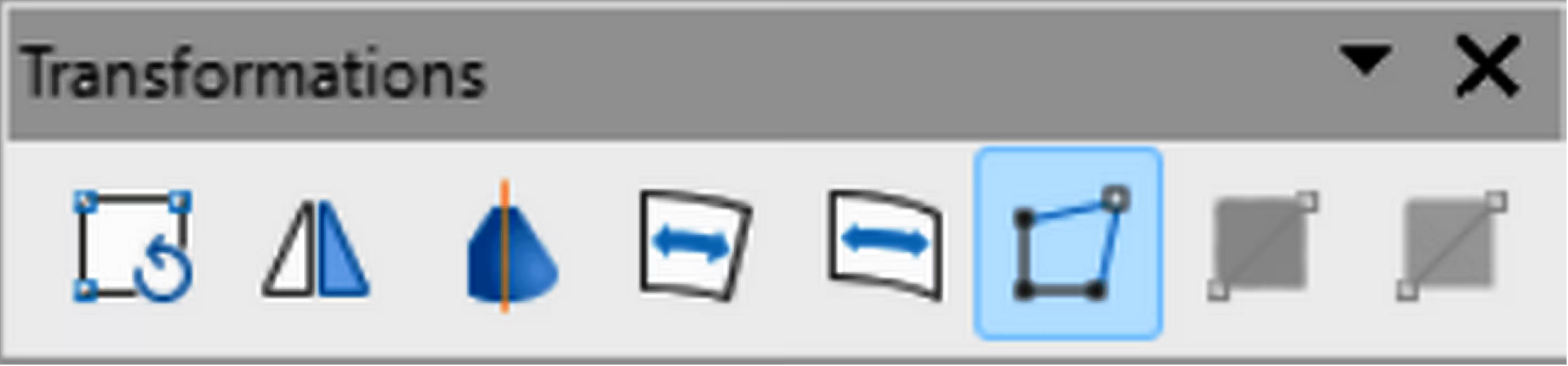
The Transformations toolbar (Figure 31) provides tools to modify the shape, orientation, or fill of selected objects.
Figure 31: Transformations toolbar
-
Rotate
-
Flip
-
In 3D Rotation Object
-
Set in Circle (perspective)
-
Set to circle (slant)
-
Distort
-
Transparency
-
Gradient
Zoom
The Zoom toolbar (Figure 33) provides tools to reduce or enlarge the screen display of the current presentation.
Figure 32: Zoom toolbar

-
Zoom In
-
Zoom Out
-
100%
-
Zoom Previous
-
Zoom Next
-
Entire Page
-
Page Width
-
Optimal View
-
Object Zoom
-
Zoom & Pan
-
Shift
Subtoolbars
3D-Objects
Click on the triangle ▼ to the right of 3D-Objects on the Drawing toolbar to open the 3D-Objects subtoolbar (Figure 34), then select a 3D object to add to a drawing. The 3D-Objects subtoolbar is identical to the 3D-Objects toolbar available at View > Toolbars on the Menu bar.
Figure 33: 3D-Objects subtoolbar
-
Cube
-
Sphere
-
Cylinder
-
Cone
-
Pyramid
-
Torus
-
Shell
-
Half Sphere
Align Objects
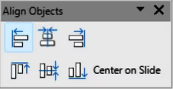
Click on the triangle ▼ to the right of Align Objects on the Drawing toolbar to open the Align Objects subtoolbar (Figure 35), then select an object alignment from the available options.
Figure 34: Align Objects subtoolbar
-
Left
-
Centered
-
Right
-
Top
-
Center
-
Bottom
Basic Shapes
Click on the triangle ▼ to the right of Basic Shapes on the Drawing toolbar to open the Basic Shapes subtoolbar (Figure 36), then select a basic shape to add to a drawing.
Figure 35: Basic Shapes subtoolbar
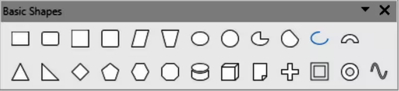
-
Rectangle
-
Rectangle, Rounded
-
Square
-
Square, Rounded
-
Parallelogram
-
Trapezoid
-
Ellipse
-
Circle
-
Circle Pie
-
Circle Segment
-
Arc
-
Block Arc
-
Isosceles Triangle
-
Right Triangle
-
Diamond
-
Regular Pentagon
-
Hexagon
-
Octagon
-
Cylinder
-
Cube
-
Folded Corner
-
Cross
-
Frame
-
Ring
Block Arrows
Click on the triangle ▼ to the right of Block Arrows on the Drawing toolbar to open the Block Arrows subtoolbar (Figure 37), then select a block arrow to add to a drawing.
Figure 36: Block Arrows subtoolbar
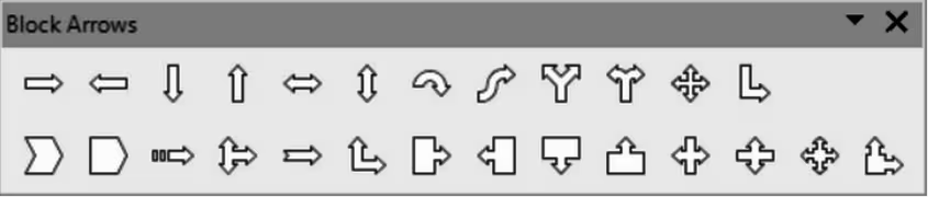
-
Right Arrow
-
Left Arrow
-
Down Arrow
-
Up Arrow
-
Left and Right Arrow
-
Up and Down Arrow
-
Circular Arrow
-
S-shaped Arrow
-
Split Arrow
-
Right or Left Arrow
-
4-way Arrow
-
Corner Right Arrow
-
Chevron
-
Pentagon
-
Striped Right Arrow
-
Up, right and Down Arrow
-
Notched Right Arrow
-
Up and Right Arrow
-
Right Arrow Callout
-
Left Arrow Callout
-
Down Arrow Callout
-
Up Arrow Callout
-
Left and Right Arrow Callout
-
Up and Down Arrow Callout
-
4-way Arrow Callout
-
Up and Right Arrow Callout
Callouts
Click on the triangle ▼ to the right of Callouts on the Drawing toolbar to open the Callouts sub‑toolbar (Figure 38), then select a callout to add to a drawing.
Figure 37: Callouts subtoolbar
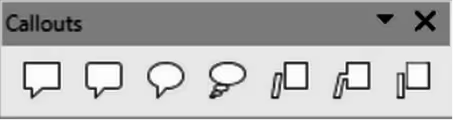
-
Rectangular Callout
-
Rounded Rectangular Callout
-
Round Callout
-
Cloud
-
Line Callout 1
-
Line Callout 2
-
Line Callout 3
Color
The Color subtoolbar (Figure 39) provides tools to edit color properties of a selected object. After selecting an image or graphic to open the Image toolbar, click on Color on the Image toolbar.
Figure 38: Color subtoolbar
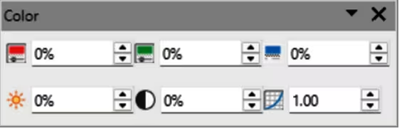
The tools available on the Color subtoolbar are as follows:
Red
Green
Blue
Brightness
Contrast
Gamma
Connectors
Click on the triangle ▼ to the right of Connectors on the Drawing toolbar to open the Connectors sub‑toolbar (Figure 40), then select a connector to add to a drawing.
Figure 39: Connectors subtoolbar

-
Connector Ends with Arrow
-
Straight Connector Ends with Arrow
-
Curved Connector Ends with Arrow
-
Line Connector Ends with Arrow
-
Connector
-
Straight Connector
-
Curved Connector
-
Line Connector
-
Connector Starts with Arrow
-
Straight Connector starts with Arrow
-
Curved Connector Starts with Arrow
-
Line Connector Starts Arrow
-
Connector Ends with Circle
-
Straight Connector Ends with Circle
-
Curved Connector Ends with Circle
-
Line Connector Ends with Circle
-
Connector Starts with Circle
-
Straight Connector starts with Circle
-
Curved Connector Starts with Circle
-
Line Connector Starts with Circle
-
Connector with Circles
-
Straight Connector with Circle
-
Curved Connector with Circle
-
Line Connector with Circle
Curves and Polygons
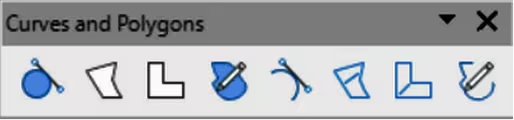
Click on the triangle ▼ to the right of Curves and Polygons on the Drawing toolbar to open the Curves and Polygons subtoolbar (Figure 41), then select a curve or polygon to add to a drawing.
Figure 40: Curves and Polygons subtoolbar
-
Curve, Filled
-
Polygon, Filled
-
Polygon (45°), Filled
-
Freeform Line, Filled
-
Curve
-
Polygon
-
Polygon (45°)
-
Freeform Line
Distribute Selection
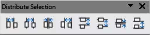
Click on the triangle ▼ to the right of Select at least three objects to distribute on the Drawing toolbar to open the Distribute Selection subtoolbar (Figure 42), then select the type of distribution required between the selected objects.
Figure 41: Distribute Selection subtoolbar
-
Distribute Horizontally Left
-
Distribute Horizontally Center
-
Distribute Horizontally Spacing
-
Distribute Horizontally Right
-
Distribute Vertically Top
-
Distribute Vertically Center
-
Distribute Vertically Spacing
-
Distribute Vertically Bottom
Flowchart
Click on the triangle ▼ to the right of Flowchart on the Drawing toolbar to open the Flowchart subtoolbar (Figure 43 ), then select a flowchart shape to add to a drawing.
Figure 42: Flowchart subtoolbar

-
Flowchart: Process
-
Flowchart: Alternate Process
-
Flowchart: Decision
-
Flowchart: Data
-
Flowchart: Predefined Process
-
Flowchart: Internal Storage
-
Flowchart: Document
-
Flowchart: Multidocument
-
Flowchart: Terminator
-
Flowchart: Preparation
-
Flowchart: Manual Input
-
Flowchart: Manual Operation
-
Flowchart: Connector
-
Flowchart: Off-page Connector
-
Flowchart: Card
-
Flowchart: Punched Tape
-
Flowchart: Summing Junction
-
Flowchart: Or
-
Flowchart: Collate
-
Flowchart: Sort
-
Flowchart: Extract
-
Flowchart: Merge
-
Flowchart: Stored Data
-
Flowchart: Delay
-
Flowchart: Sequential Access
-
Flowchart: Magnetic Disc
-
Flowchart: Direct Access Storage
-
Flowchart: Display
Fontwork Shape
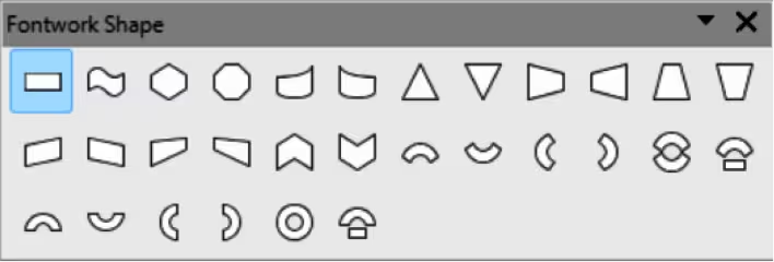
Clicking on the triangle ▼ to the right of Fontwork Shape on the Fontwork toolbar opens the Fontwork Shape subtoolbar (Figure 44). Select the required shape to change how a Fontwork text shape appears on a slide.
Figure 43: Fontwork Shape subtoolbar
-
Plain Text
-
Wave
-
Inflate
-
Stop
-
Curve Up
-
Curve Down
-
Triangle Up
-
Triangle Down
-
Fade Right
-
Fade Left
-
Fade Up
-
Fade Down
-
Slant Up
-
Slant Down
-
Fade Up and Right
-
Fade Up and Left
-
Chevron Up
-
Chevron Down
-
Arch Up (Curve)
-
Arch Down (Curve)
-
Arch Left (Curve)
-
Arch Right (Curve)
-
Circle (Curve)
-
Open Circle (Curve)
-
Arch Up (Pour)
-
Arch Down (Pour)
-
Arch Left (Pour)
-
Arch Right (Pour)
-
Circle (Pour)
-
Open Circle (Pour)
Image Filter
Clicking on the triangle ▼ to the right of Filter on the Image toolbar opens the Image Filter sub‑toolbar (Figure 45). Select the required filter to change the image display.
Figure 44: Image Filter subtoolbar

The image filters available on the Image Filter subtoolbar are as follows, from left to right:
Invert
Smooth
Sharpen
Remove Noise
Solarization
Aging
Posterize
Pop Art
Charcoal Sketch
Relief
Mosaic
Lines and Arrows
Click on the triangle ▼ to the right of Lines and Arrows on the Drawing toolbar to open the Lines and Arrows subtoolbar (Figure 46), then select a line or arrow to add to a drawing.
Figure 45: Lines and Arrows subtoolbar

-
Line Ends with Arrow
-
Line with Circle/Arrow
-
Line with Square/Arrow
-
Line with Arrows
-
Line Starts with Arrow
-
Line with Arrow/Circle
-
Line with Arrow/Square
-
Insert Line
-
Dimension Line
-
Line (45°)
Optimize
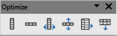
Click on the triangle ▼ to the right of Optimize on the Table toolbar to open the Optimize subtoolbar (Figure 46) to evenly distribute selected rows and columns in a table either horizontally or vertically.
Figure 46: Optimize subtoolbar
-
Minimal Column Width
-
Minimal Row Height
-
Optimal Column Width
-
Optimal Row Height
-
Distribute Columns Evenly
-
Distribute Rows Evenly
Position
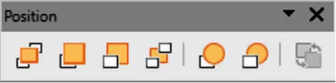
Click on the triangle ▼ to the right of Arrange on the Standard toolbar to open the Position subtoolbar (Figure 47), then select the position of a selected object in a drawing. These tools are also available on the Drawing toolbar.
Figure 47: Position subtoolbar
-
Bring to Front
-
Bring Forward
-
Send Backward
-
Send to Back
-
In Front of Object
-
Behind Object
-
Reverse
Stars and Banners
Click on the triangle ▼ to the right of Stars and Banners on the Drawing toolbar to open the Stars and Banners subtoolbar (Figure 48), then select a star or arrow to add to a drawing.
Figure 48: Stars and Banners subtoolbar

-
4-Point Star
-
5-Point Star
-
6-Point Star
-
8-Point Star
-
12-Point Star
-
24-Point Star
-
Explosion
-
Vertical Scroll
-
Horizontal Scroll
-
Signet
-
Doorplate
-
6-Point Star, Concave
Symbol Shapes
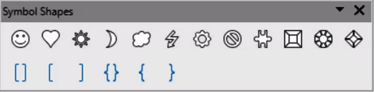
Click on the triangle ▼ to the right of Symbol Shapes on the Drawing toolbar to open the Symbol Shapes subtoolbar (Figure 49), then select a symbol shape to add to a drawing.
Figure 49: Symbol Shapes subtoolbar
-
Smiley Face
-
Heart
-
Sun
-
Moon
-
Cloud
-
Lightning Bolt
-
Flower
-
Prohibited
-
Puzzle
-
Square Bevel
-
Octagon Bevel
-
Diamond Bevel
-
Double Bracket
-
Left Bracket
-
Right Bracket
-
Double Brace
-
Left Brace
-
Right Brace