Impress Guide 7.4
Chapter 5,
Managing Graphic Objects
This document is Copyright © 2022 by the LibreOffice Documentation Team. Contributors are listed below. This document maybe distributed and/or modified under the terms of either the GNU General Public License (https://www.gnu.org/licenses/gpl.html), version 3 or later, or the Creative Commons Attribution License (https://creativecommons.org/licenses/by/4.0/), version 4.0 or later. All trademarks within this guide belong to their legitimate owners.
Contributors for this edition:
Peter Schofield
Kees Kriek
Contributors for previous editions:
Peter Schofield
Kees Kriek
Samantha Hamilton
Michele Zarri
Jean Hollis Weber
T. Elliot Turner
Low Song Chuan
Vasudev Narayanan
Rachel Kartch
Please direct any comments or suggestions about this document to the Documentation Team mailing list: loguides@community.documentfoundation.org.
Note
Everything sent to a mailing list, including email addresses and any other personal information that is written in the message, is publicly archived and cannot be deleted.
Published October 2022. Based on LibreOffice 7.4 Community.
Other versions of LibreOffice may differ in appearance and functionality.
Some keystrokes and menu items are different on macOS from those used in Windows and Linux. The table below gives some common substitutions used in this document. For a detailed list, see LibreOffice Help.
|
Windows or Linux |
macOS equivalent |
Effect |
|
Tools > Options |
LibreOffice > Preferences |
Access setup options |
|
Right-click |
Control+click, Ctrl+click, or right-click depending on computer setup |
Open a context menu |
|
Ctrl or Control |
⌘ and/or Cmd or Command, depending on keyboard |
|
|
Alt |
⌥ and/or Alt or Option depending on keyboard |
Used with other keys |
|
F11 |
⌘+T |
Open the Styles deck in the Sidebar |
This chapter describes how to rotate, distort, arrange, and position graphic objects on a slide using the available tools in Impress. However, some of the techniques described in this chapter are also applicable to images imported into slides.
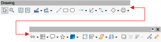
The Drawing toolbar (Figure 1) contains the majority of the tools normally used to create graphic objects. If this toolbar is not visible, select View > Toolbars > Drawing from the Menu bar. By default, the Drawing toolbar is docked vertically at the left side of the Impress window.
Figure 1: Drawing toolbar
Note
The Drawing toolbar shown in Figure 1 may differ between different operating systems and computer setup. Also, the Drawing toolbar displayed depends on how many drawing tools have been placed on the toolbar. Right-click in an empty area of the Drawing toolbar, then select Visible Buttons from the context menu to display, install and remove available tools. See Appendix B, Toolbars and the Getting Started Guide for more information on customizing toolbars in Impress.
From left to right, the drawing tools shown in Figure 1 are as follows:
Select
Zoom & Pan
Insert Text Box
Insert Vertical Text
Line Color
Fill Color
Insert Line
Rectangle
Ellipse
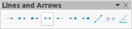
Line and Arrows
Figure 2: Lines and Arrows sub-toolbar
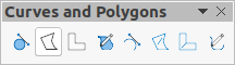
Curves and Polygons
Figure 3: Curves and Polygons sub-toolbar
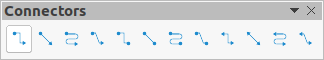
Connectors
Figure 4: Connectors sub-toolbar
Basic Shapes
Figure 5: Basic Shapes sub-toolbar

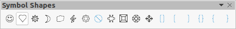
Symbol Shapes
Figure 6: Symbol Shapes sub-toolbar
Block Arrows
Figure 7: Block Arrows sub-toolbar

Flowchart
Figure 8: Flowchart sub-toolbar

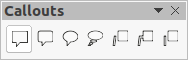
Callout Shapes
Figure 9: Callouts sub-toolbar
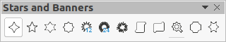
Stars and Banners
Figure 10: Stars and Banners sub-toolbar
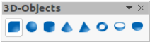
3D-Objects
Figure 11: 3D-Objects sub-toolbar
Rotate
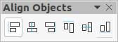
Align Objects
Left, Centered, Right
Determines the horizontal alignment of selected objects.
Top, Center, Bottom
Determines the vertical alignment of selected objects.
Figure 12: Align Objects sub-toolbar
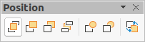
Arrange
Bring to front
Selected object is moved in front of all other objects.
Bring forward
Selected object is moved one level up in the stack.
Send backwards
Send to back
Selected object is moved behind all other objects.
In front of object
Moves the first selected object in front of the second selected object.
Behind object
Moves the first selected object behind the second selected object.
Reverse
Swaps the stacking order of two selected objects.
Figure 13: Position sub-toolbar
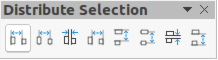
Distribute Selection
Figure 14: Distribute Selection sub-toolbar
Shadow
Crop Image
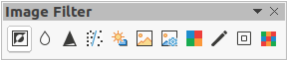
Filter
Invert
Inverts the color values of a color image, or the brightness values of a grayscale image. Apply the filter again to reverse the effect.
Smooth
Softens or blurs the image by applying a low pass filter.
Figure 15: Image Filter toolbar
Sharpen
Sharpens the image by applying a high pass filter.
Remove Noise
Removes noise by applying a median filter.
Solarization
Opens a dialog for defining solarization. Solarization refers to an effect that looks like what can happen when there is too much light during photo development.
Aging
All pixels are set to their gray values. The green and blue color channels are then reduced by the amount you specify. The red color channel is not changed.
Posterize
Opens a dialog to determine the number of poster colors. This effect is based on the reduction of the number of colors. It makes photos look like paintings.
Pop Art
Converts an image to a pop-art format.
Charcoal Sketch
Displays the image as a charcoal sketch. The contours of the image are drawn in black, and the original colors are suppressed.
Relief
Displays a dialog for creating reliefs. You can choose the position of the imaginary light source that determines the type of shadow created, and how the graphic image looks in relief.
Mosaic
Joins small groups of pixels into rectangular areas of the same color. The larger the individual rectangles are, the fewer details the graphic image has.
Points
Show Gluepoints Functions
Figure 16: Gluepoints toolbar
Toggle Extrusion
Figure 17: 3D-Settings toolbar
This section is an introduction to creating lines and shapes. For more information on working with lines and shapes, see the Draw Guide.
Regular shapes that are available on the Drawing toolbar are as follows:
Rectangle
Ellipse
Basic Shapes
Symbol Shapes
Block Arrows
Flowchart
Callouts Shapes
Stars and Banners
3D Objects
Some icons for regular shapes have a triangle ▼ next to the icon that gives access to several different types of regular shapes. Also, the icons for some of the regular shapes displayed on the Drawing toolbar show the last tool used for each of these regular shapes.
Drawing a regular shape is as follows:
1) Select the required tool from the Drawing toolbar or a sub-toolbar after selecting the triangle ▼ next to the icon.
2) Place the cursor on the slide, then click and drag to define an enclosing rectangle.
3) Release the cursor and the selected shape is drawn on the slide.
4) Press and hold the Shift key when creating a shape to maintain equal height and width. For example, using Rectangle or Ellipse to draw a square or a circle. Release the cursor before releasing the Shift key.
5) Press and hold the Alt key (macOS ⌥) to draw a shape from its center. Release the cursor before releasing the Alt key (macOS ⌥).
6) Press and hold the Shift and Alt (macOS ⌥) keys when creating a shape to maintain equal height and width and draw the shape from the center. For example, when using Rectangle or Ellipse tool to draw a square or a circle. Release the cursor before releasing the Shift and Alt (macOS ⌥) keys.
7) Press and hold the Ctrl key (macOS ⌘) when creating a shape to snap the top left corner of the shape selection box to the nearest grid point.
Note
If the Snap to Grid option in Tools > Options > LibreOffice Impress > Grid (macOS LibreOffice > Preferences > LibreOffice Impress > Grid) has been selected, pressing and holding the Ctrl key (macOS ⌘) prevents the top left corner of the shape selection box snapping to the nearest grid point.
When creating shapes that are included in Impress, one or more dots maybe displayed in a different color to the selection handles. These dots perform a different function according to the shape they are applied to and are listed below.
The Basic Shapes with shape adjustment dots are as follows:
Rectangle, Rounded
Square, Rounded
Parallelogram
Trapezoid
Circle Pie
Block Arc
Isosceles Triangle
Hexagon
Octagon
Cylinder
Cube
Folded Corner
Cross
Frame
Ring
The Symbol Shapes with shape adjustment dots are as follows:
Smiley Face
Sun
Moon
Prohibited
Square Bevel
Octagon Bevel
Diamond Bevel
Double Bracket
Left Bracket
Right Bracket
Double Brace
Left Brace
Right Brace
The Block Arrows with shape adjustment dots are as follows:
Right Arrow
Left Arrow
Down Arrow
Up Arrow
Left and Right Arrow
Up and Down Arrow
Circular Arrow
4-way Arrow
Chevron
Pentagon
Striped Right Arrow
Up, Right and Down Arrow
Notched Right Arrow
Up and Right Arrow
Right Arrow Callout
Left Arrow Callout
Down Arrow Callout
Up Arrow Callout
Left and Right Arrow Callout
Up and Down Arrow Callout
4-way Arrow Callout
Up and Right Arrow Callout
All Callouts use shape adjustment dots to change the length, position and angle of the pointer.
The Stars and Banners with shape adjustment dots are as follows:
4-Point Star
8-Point Star
24-Point Star
Vertical Scroll
Horizontal Scroll
Doorplate
Curves, polygons and lines on the Drawing toolbar have a triangle ▼ next to the icon. Clicking on this triangle ▼ opens a sub-toolbar giving access to several different types of curves, polygons and lines. The icons on the Drawing toolbar show the last tool used for each of these curves, polygons and lines. If a filled curve, filled polygon, or filled freeform line was selected, Impress draws the line connecting the last point to the start point and fills the inside area with the default fill color.
1) Click the triangle ▼ next to Curves and Polygons on the Drawing toolbar to open the Curves and Polygons sub-toolbar.
2) Select either Curve or Curve Filled.
3) Place the cursor on the slide, then click and drag to create the starting point of a curve.
4) Release the cursor and drag the cursor to draw a curve on the slide, bending the line into a curve.
5) Click to set the end point of the curve and fix the curve on the slide.
6) Drag the cursor to continue drawing a straight line. Each click sets a corner point and allows drawing of another straight line from the corner point.
7) Double-click to end the drawing of the curve. If Curve Filled was selected, Impress automatically fills the curve with the default fill color.
Note
Holding down the Shift key when drawing lines with the curve or polygon tools restricts the angles between lines to 45 or 90 degrees.
1) Click the triangle ▼ next to Curves and Polygons on the Drawing toolbar to open the Curves and Polygons sub-toolbar.
2) Select either Polygon, Polygon Filled, Polygon (45°) or Polygon Filled (45°).
3) Place the cursor on the slide, then click and drag to draw the first line from the start point. Release the cursor and a line between the first and second points is drawn.
4) Move the cursor to draw the next line. Each click sets a corner point and allows drawing of another line.
5) Double-click to end the drawing of a polygon. If Polygon Filled or Polygon Filled (45°) was selected, Impress automatically fills the polygon with the default fill color.
Note
If Polygon (45°) or Polygon Filled (45°) were selected, the movement of the cursor and the angles between lines is restricted to increments of 45°.
Using Freeform Line or Freeform Line Filled tools is similar to drawing with a pencil on paper.
1) Click the triangle ▼ next to Curves and Polygons on the Drawing toolbar to open the Curves and Polygons sub-toolbar.
2) Select either Freeform Line or Freeform Line Filled.
3) Click and drag the cursor to the line shape required.
4) When finished drawing a freeform line, release the cursor and the drawing is completed. If Freeform Line Filled was selected, Impress automatically fills the drawing between the start and end points with the default fill color.
A straight line is the simplest element or object in Impress to create.
1) Use one of the following methods to draw a line:
Click Insert Line in the Drawing toolbar.
Click the triangle ▼ on the right of Lines and Arrows on the Drawing toolbar and select Insert Line from the Lines and Arrows sub-toolbar.
2) Click at the start position for the line and drag the cursor.
3) Release the cursor at the end position of the line. A selection handle appears at each end of the line. The selection handle at the starting point of the line is larger than the selection handle at the end point.
4) Keep the Ctrl key (macOS ⌘) pressed while drawing a line to enable the end of the line to snap to the nearest grid point.
5) Keep the Shift key pressed while drawing a line to restrict the drawing angle of a line to multiple of 45 degrees.
6) Keep the Alt key (macOS ⌥) pressed while drawing a line to cause the line to extend outwards symmetrically in both directions from the start point. This draws lines by starting from the middle of the line.
Arrows are drawn like lines and are classified as a subgroup of lines, that is lines with arrowheads. Hovering the cursor over each type of arrow that is available shows the type of endings each tool will draw.
1) Click the triangle ▼ on the right of Lines and Arrows on the Drawing toolbar and select the type of arrow from the Lines and Arrows sub-toolbar.
2) Click at the starting position for drawing the arrow, then drag the cursor. The arrowhead(s) is drawn at the end of the line when the cursor is released.
3) Keep the Ctrl key (macOS ⌘) pressed while drawing an arrow to enable the end of the arrow to snap to the nearest grid point.
4) Keep the Shift key pressed while drawing an arrow to restrict the drawing angle of an arrow to multiple of 45 degrees.
5) Keep the Alt key (macOS ⌥) pressed while drawing an arrow to cause the arrow to extend outwards symmetrically in both directions from the start point. This draws arrows by starting from the middle of the arrow.
Note
If the Snap to Grid option in Tools > Options > LibreOffice Impress > Grid (macOS LibreOffice > Preferences > LibreOffice Impress > Grid) has been selected, pressing and holding the Ctrl key (macOS ⌘) whilst drawing a line or arrow has the opposite effect and prevents the line or arrow snapping to the nearest grid point.
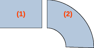
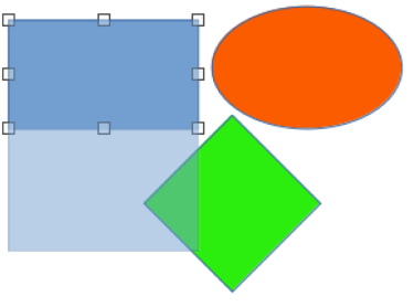
Figure 18: Example of grouping objects
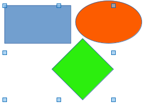
This section gives only a brief introduction to grouping of objects. An example of grouping two objects together is shown in Figure 18. For more information on working with grouped objects, see the Draw Guide.
Grouping of objects is similar to putting objects into a container. Objects within a group are moved together as one object and any changes made are applied globally to the objects within the group. A group can always be undone and the objects that make up the group can always be manipulated separately.
Temporary grouping is when several objects are selected together. Any changes to the objects are applied to all of the objects within the temporary group. For example, a temporary group of objects can be rotated in its entirety.
A temporary group is created using one of the following methods:
Hold down the Shift key whilst clicking multiple objects on a slide.
Click and drag the cursor to create a marquee around multiple objects. Release the cursor and all the objects within the marquee are selected.
To cancel a temporary grouping of objects, simply click outside of the selection handles displayed around the objects.
1) Objects are grouped together using one of the following methods:
Hold down the Shift key whilst clicking multiple objects on a slide.
Click and drag the cursor to create a marquee around multiple objects. Release the cursor and all the objects within the marquee are selected.
To select all the objects on the slide, go to Edit > Select All on the Menu bar, or use the keyboard shortcut Ctrl+A (macOS ⌘+A).
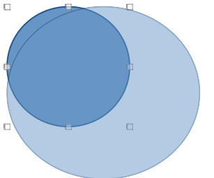
Figure 19: Example of editing inside a group
2) With selection handles displayed, use one of the following methods to create a group of selected objects:
Go to Format > Group > Group on the Menu bar.
Use the keyboard shortcut Ctrl+Shift+G (macOS ⌘+Shift+G).
Right-click on an object within the selected group and select Group from the context menu.
1) Click on an object in the group to select the group. Any editing or formatting can then be carried out on all the objects within the group or on individual objects within the group.
2) To edit an individual object within a group, enter the group using one of the following methods:
Use the keyboard shortcut F3.
Go to Format > Group > Enter Group on the Menu bar.
Right-click and select Enter Group from the context menu.
3) Select individual objects within the group for editing or formatting. An example of editing individual objects in a group is shown in Figure 19.
4) When editing or formatting is completed, use one of the following methods to exit the group and the whole group then becomes selected:
Use the keyboard shortcut Ctrl+F3 (macOS ⌘+F3).
Go to Format > Group > Exit Group on the Menu bar.
Right-click and select Exit Group from the context menu.
1) Click on any one of the objects in the group to select the group.
2) With selection handles displayed, use one of the following methods to ungroup a group of objects:
Go to Format > Group > Ungroup on the Menu bar.
Use the keyboard shortcut Ctrl+Alt+Shift+G (macOS ⌘+⌥+Shift+G).
Right-click on the group and select Ungroup from the context menu.
Tip
If group and ungroup commands are regularly used, or any other command, commands can be added to a toolbar so that they are readily available. See Chapter 11, Setting Up and Customizing Impress; Appendix B, Toolbars; and the Getting Started Guide for more information on customizing the user interface.
1) Click on an object or a group of objects to display the selection handles.
2) Move the cursor over a selected graphic object until the cursor changes shape. The cursor shape depends on the computer setup and the computer operating system.
3) Click and drag the object to the desired position. During movement, a ghost image of the object appears to help with repositioning (Figure 20).
4) Release the cursor when the object is in the desired position.
Note
The arrow keys can also be used to quickly move a selected object or group to a new position.
1) Click on an object or a group of objects to display the selection handles.
2) Move the cursor over a selection handle.
Figure 20: Example of moving objects
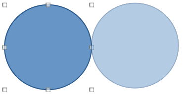
Figure 21: Example of resizing an object
3) Click and drag the selection handle to resize the graphic object. During resizing, a ghost image of the object appears to help with resizing (Figure 21).
4) To maintain the width to height ratio, hold down the Shift key before clicking and dragging on a selection handle. Remember to release the cursor before releasing the Shift key.
5) Release the cursor when the object is at the desired size.
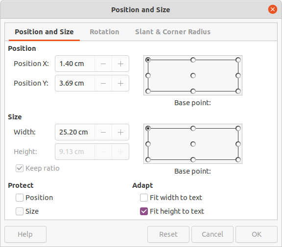
For a more accurate placement of a graphic object on a slide, use the Position and Size dialog (Figure 22) as follows:
1) Select an object to display the selection handles and open the Position and Size dialog using one of the following methods:
Use the keyboard shortcut F4.
Go to Format > Text Box and Shape > Position and Size on the Menu bar.
Right-click on the selected object and select Position and Size from the context menu.
Click on More Options on the right of the title bar for the Position and Size panel in the Properties deck on the Sidebar.
2) Click on the Position and Size tab to open the Position and Size page.
3) In the Position section, specify Position X (horizontal) and Position Y (vertical) position of the object. The values represent the distance from the Base point selected on the right hand side of the dialog. The default selection for Base point is relative to the top left corner of the slide.
4) If necessary, in the Protect section of the dialog, select the Position option to prevent the object from being repositioned.
5) Click OK to save the changes and to close the dialog.
Figure 22: Position and Size dialog - Position and Size page
Note
The units of measurement used in this dialog and other Impress dialogs are set in Tools > Options > LibreOffice Impress > General (macOS LibreOffice > Preferences > LibreOffice Impress > General).
1) Select an object to display the selection handles and open the Position and Size dialog using one of the following methods:
Use the keyboard shortcut F4.
Go to Format > Text Box and Shape > Position and Size on the Menu bar.
Right-click on the selected object and select Position and Size from the context menu.
Click on More Options on the right of the title bar for the Position and Size panel in the Properties deck on the Sidebar.
2) Click on the Position and Size tab to open the Position and Size page.
3) In Size, select a Base point to use as an anchor when resizing the object. The default selection of top left corner means that the top left corner of the object will not change position when resizing.
4) To maintain the proportions between width and height, in the Size section select the Keep ratio option before changing the Width or Height. When Keep ratio is selected, changing the value of one dimension automatically changes the other dimension maintaining the ratio between object width and height.
5) To specify the object width or height independently, make sure Keep ratio is deselected, then, in the Size section, enter a value for the Width and/or Height of the object.
6) If necessary, in the Protect section of the dialog, select the Size option to prevent the object from being resized.
7) Click OK to save the changes and to close the dialog.
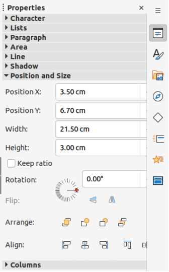
Use the Position and Size panel in the Properties deck on the Sidebar (Figure 23) to position and resize a graphic object.
1) Select an object to display the selection handles.
2) Click on Properties in the Sidebar to open the Properties deck.
3) Click on Position and Size to open the panel.
4) Specify Position X (horizontal) and Position Y (vertical) position of the object. The values represent the distance from the Base point that has been selected in the Position and Size dialog.
5) Press the Enter key to make the changes.
Figure 23: Position and Size panel in Properties deck on Sidebar
1) Select an object to display the selection handles.
2) Click on Properties in the Sidebar to open the Properties deck.
3) Click on Position and Size to open the panel.
4) To maintain the proportions between width and height, select the Keep ratio option before changing the Width or Height. When Keep ratio is selected, changing the value of one dimension automatically changes the other dimension maintaining the ratio between object width and height.
5) To specify the object width or height independently, make sure Keep ratio is deselected, then, enter a value for the Width and/or Height of the object.
6) Press the Enter key to make the changes.
As well as the basic actions of moving and resizing an object, a number of special effects can also be applied to objects in Impress. This section describes how to rotate, flip, and distort an object.
1) Select an object to display the selection handles.
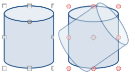
2) On the Line and Filling toolbar, click on the triangle ▼ next to Transformations then click on Rotate on the Transformations sub-toolbar. The selection handles change shape and color as shown in Figure 24. A pivot point indicating the rotation center also appears in the center of the object.
3) Move the cursor over one of the corner handles and the cursor changes shape indicating the movement direction.
4) Click on a corner selection handle and move in the direction required to rotate the object. Only the corner selection handles are active for rotation.
5) When satisfied with the rotation, release the cursor.
6) To change the rotation center of the object, click and drag the pivot point to the desired position before rotating. The pivot point can be moved to any position on the slide, even outside of the object boundaries.
Figure 24: Example of rotating objects
7) To restrict the rotation angles to multiples of 15 degrees, press and hold the Shift key while rotating the object. This is useful for rotating pictures through a right angle, for example from portrait to landscape. Remember to release the Shift key before releasing the cursor.
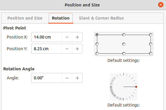
Instead of rotating an object manually, use the Rotation page of the Position and Size dialog (Figure 25) to accurately rotate an object.
1) Select an object to display the selection handles, then open the Position and Size dialog using one of the following methods:
Use the keyboard shortcut F4.
Go to Format > Text Box and Shape > Position and Size on the Menu bar.
Right-click on the selected object and select Position and Size from the context menu.
Click on More Options on the right of the title bar for the Position and Size panel in the Properties deck on the Sidebar.
2) Click on the Rotation tab to open the Rotation page.
3) If necessary, in Pivot Point enter a measurement for Position X and Position Y to move the position of the pivot point. The default position of the pivot point is the center of the object. Alternatively, select a pivot point from one of the 9 positions in Default settings.
4) In Rotation Angle, enter the degree amount for rotation in the Angle text box. Alternatively, in Default settings, click on the rotation angle indicator and drag it to a new angle. The angle of rotation is displayed in the Angle text box.
5) Click OK to save the changes and to close the dialog.
Use the Position and Size panel in the Properties deck on the Sidebar (Figure 23 above) to rotate an object as follows:
1) Select an object to display the selection handles.
Figure 25: Position and size dialog - Rotation page
2) Click on Properties in the Sidebar to open the Properties deck.
3) Click on Position and Size to open the panel.
4) In Rotation, enter the degree amount for rotation in the text box or click on the rotation angle indicator and drag it to a new angle. The angle of rotation is displayed in the Rotation text box.
5) Press the Enter key to make the changes.
1) Click on an object to display the selection handles.
2) Quickly flip a selected object so it faces the other direction using one of the following methods:
Right-click on the selected object and select Flip > Vertically or Horizontally from the context menu.
Click on Vertically or Horizontally flip tool on the Standard toolbar.
Go to Format > Flip > Vertically or Horizontally on the Menu bar.
Click on Flip Vertically or Flip Horizontally in the Position and Size panel on the Properties deck of the Sidebar.
To change the position and angle that an object flips over, the Flip tool on the Transformations toolbar (Figure 26) is used as shown by the example in Figure 27.
1) Click on an object to display the selection handles.
2) Go to View > Toolbars > Transformations to open the Transformations toolbar.
3) Click on Flip on the Transformations toolbar and a symmetry axis appears as a dashed line through the center of the object (Item (1) in Figure 27). The object is flipped about this axis of symmetry.
Figure 26: Transformations toolbar
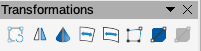
Figure 27: Example of using the Flip tool
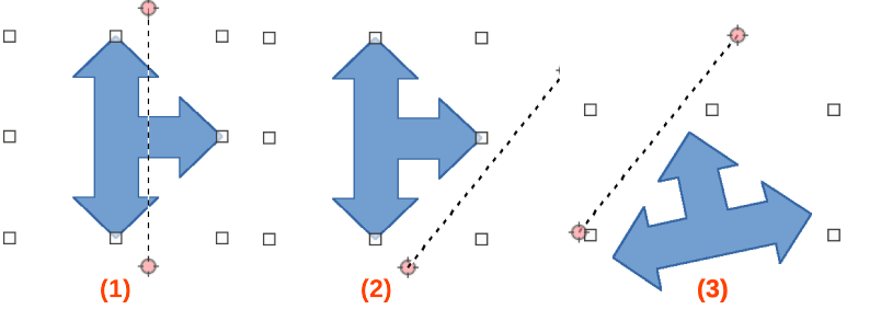
4) Click and drag the symmetry axis to a new position, or position the cursor in one of the circles at each end of the symmetry axis and drag with the cursor to change the angle (Item (2) in Figure 27).
5) Place the cursor over one of the selection handles for the object.
6) Click and drag the cursor across the symmetry axis to flip the object. The new position of the object is shown faintly until the cursor is released.
7) Release the cursor and the object appears flipped over. Angle and position of the flip depends on the angle and position of the symmetry axis (Item (3) in Figure 27).
Note
Press and hold the Shift key while moving the symmetry axis to rotate it in 45 degree increments.
Impress does not include a mirror command. However, mirroring an object can be emulated by flipping the object:
1) Select the object to make a mirror copy and copy the object to the clipboard.
2) Flip the object using one of the methods in “Quick flipping” on page 1, then move the flipped object to one side.
3) Click in an empty area of the slide to deselect the object.
4) Paste the copied object from the clipboard into the slide.
5) Select both objects, then right-click and select Alignment from the context menu.
6) Select the type of alignment required. Top, Center, or Bottom if a horizontal mirror copy is being created. Left, Centered, or Right if a vertical mirror copy is being created.
Three tools on the Transformations toolbar allow an object to be distorted.
Distort – distorts an object in perspective.
Set to circle (slant) and Set in Circle (perspective) – both create a pseudo 3D effect.
Note
When using these tools, an object has to be converted to a curve before distorting. Converting an object into a curve cannot be reversed and can only be undone by using the Undo function.
Examples of corner, vertical, and horizontal distortion of an object using the Distort tool are shown in Figure 28.
1) Select an object and click on Distort on the Transformations toolbar.
2) Click Yes to convert the object to a curve. If the object is already a curve, this dialog does not appear.
3) Click and drag a corner selection handle to distort the object using the opposite corner selection handle as an anchor point for the distortion.
Figure 28: Example of object distortion
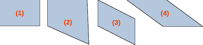
Original shape
Corner distortion
Vertical distortion
Horizontal distortion
4) Click and drag the vertical selection handles to distort the object using the opposite vertical side as an anchor point for the distortion.
5) Click and drag the horizontal selection handles to distort the object using the opposite horizontal side as an anchor point for the distortion.
Example of distorting an object using the Set in Circle (perspective) tool is shown in Figure 29.
1) Select an object and click on Set in Circle (perspective) in the Transformations toolbar.
2) Click Yes to convert the object to a curve. If the object is already a curve, this dialog does not appear.
3) Click and drag one of the selection handles to give a pseudo 3D perspective using the opposite side as an anchor point. A ghosted image appears as the object is distorted to give an indication of how the resulting object will look.
Example of distorting an object with the Set to circle (slant) tool is shown in Figure 30.
1) Select an object and click on Set to circle (slant) in the Transformations toolbar.
2) Click Yes to convert the object to a curve. If the object is already a curve, this dialog does not appear.
3) Click and drag one of the selection handles to give a pseudo 3D perspective using the opposite side as an anchor point. A ghosted image appears as the object is distorted to give an indication of how the resulting object will look.
Use the alignment tools in LibreOffice to adjust the relative position of an object compared to another object. These alignment tools are only active if two or more objects are selected. The alignment options are as follows:
Left, Centered, Right — determines the horizontal alignment of selected objects.
Top, Center, Bottom — determines the vertical alignment of selected objects.
Select two or more objects for alignment and use one of the following methods to access the align options:
Click on the triangle ▼ next to Align Objects on the Line and Filling toolbar. Select an alignment option from the tools available. The Align Objects icon shown on the Line and Filling toolbar depends on the last tool used.
Go to View > Toolbars > Align Objects on the Menu bar to open the Align Objects toolbar. Select an alignment option from the tools available.
Right-click on the group of selected objects and select Align Objects and then one of the alignment options from the context menu.
In Impress, objects can be positioned accurately and consistently using grid points, snap points and lines, object frames, individual points on objects, or page edges. This function is known as Snap. It allows positioning of an object in exactly the same place on multiple slides.
It is easier to use snap functions at the highest practical zoom value for a presentation. Two different snap functions can be used at the same time. For example, snapping to a guide line and the slide edge. It is recommended to activate only those snap functions that are really required.
To configure the grid and snap in a presentation, go to Tools > Options > LibreOffice Impress > Grid (macOS LibreOffice > Preferences > LibreOffice Impress > Grid) on the Menu bar to display the Grid dialog (Figure 31).
Grid
Snap to grid
Specifies how frames, drawing elements, and controls are moved between grid points. To change the status of Snap to grid only for the current action, drag an object while holding down the Ctrl key (macOS ⌘).
Visible grid
Specifies how the grid is displayed.
Figure 31: Options LibreOffice Impress Grid dialog
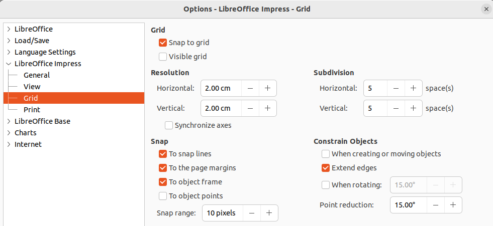
Resolution
Horizontal
Vertical
Subdivision
Horizontal
Specify the number of intermediate spaces between grid points on the X‑axis.
Vertical
Specify the number of intermediate spaces between grid points on the Y‑axis.
Synchronize axes
Specifies how the current grid settings are changed symmetrically. The resolution and subdivision for the X and Y axes remain the same.
Snap
To snap lines
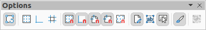
Snaps the edge of a dragged object to the nearest snap line when the cursor is released. Also, this setting can be defined by using Snap to Snap Guides on the Options toolbar (Figure 32).
Figure 32: Options toolbar
To the page margins
Specifies whether to align the contour of the graphic object to the nearest page margin. The cursor or a contour line of the object must be in the snap range. In a presentation, this function can also be accessed with Snap to page Margins in the Options toolbar.
To object frame
Specifies whether to align the contour of the object to the border of the nearest object. The cursor or a contour line of the object must be in the snap range. In a presentation, this function can also be accessed with Snap to Object Border in the Options toolbar.
To object points
Specifies whether to align the contour of the object to the points of the nearest object. This only applies if the cursor or a contour line of the object is in the snap range. In a presentation, this function can also be accessed with Snap to Object Points in the Options toolbar.
Snap range
Defines the snap distance between the cursor and the object contour. Snaps to a snap point if the cursor is closer than the distance selected.
Constrain Objects
When creating or moving objects
Specifies that objects are restricted vertically, horizontally or diagonally (45°) when creating or moving them. This setting can be temporarily deactivated by pressing and holding the Shift key.
Extend edges
Specifies that a square is created based on the longer side of a rectangle when the Shift key is pressed before releasing the cursor. This also applies to an ellipse (a circle will be created based on the longest diameter of the ellipse). When Extend edges is not selected, a square or a circle is created based on the shorter side or diameter.
When rotating
Specifies that objects can only be rotated within the rotation angle that is selected. To rotate an object outside the defined angle, press the Shift key when rotating. Release the Shift key when the desired rotation angle is reached.
Point reduction
Defines the angle for point reduction. When working with polygons, this is useful in reducing the editing points.
The grid and snap functions can also be displayed and switched on or off using one of the following methods:
Go to Tools > Options > LibreOffice Impress > Grid (macOS LibreOffice > Preferences > LibreOffice Impress > Grid) on the Menu bar to display the Grid dialog.
Right-clicking on a slide and using the options in the context menu.
Using the tools in the Options toolbar.
Use the Snap to Grid function to move an object exactly onto a grid point in a slide. This function can be switched on and off using one of the following methods:
Go to View > Snap Guides > Snap to Grid on the Menu bar.
Right-click on a slide and select Snap Guides > Snap to Grid from the context menu.
Click on Snap to Grid on the Options toolbar.
To display or turn off the grid in a presentation using one of the following methods:
Go to View > Grid and Helplines > Display Grid on the Menu bar.
Click on Display Grid on the Options toolbar.
Right-click on a slide and select Grid and Helplines > Display Grid from the context menu.
Select Visible grid option in Tools > Options > LibreOffice Impress > Grid (macOS LibreOffice > Preferences > LibreOffice Impress > Grid).
By default and depending on the display and computer setup, the grid points are gray and are not always easy to see. To change the color of the grid points, go to Tools > Options > LibreOffice > Application Colors (macOS LibreOffice > Preferences > LibreOffice > Application Colors) to open the Options LibreOffice Application Colors dialog (Figure 33). In the Drawing/Presentation section, select a more suitable color for the grid from the drop-down list to make the grid points more prominent against the color scheme being used.
Unlike the grid, snap lines and snap points are inserted when positioning an object to a specific position on a slide. Snap lines can either be horizontal or vertical and appear as dashed lines. Snap points appear as small crosses with dashed lines. Snap points and snap lines do not appear in printed output.
To insert a snap point or line use one of the following methods to open the New Snap Object dialog (Figure 34):
Go to Insert > Snap Guide on the Menu bar.
Right-click in an empty space on a slide and select Insert Snap Guide from the context menu.
Figure 33: Options LibreOffice Application Colors dialog
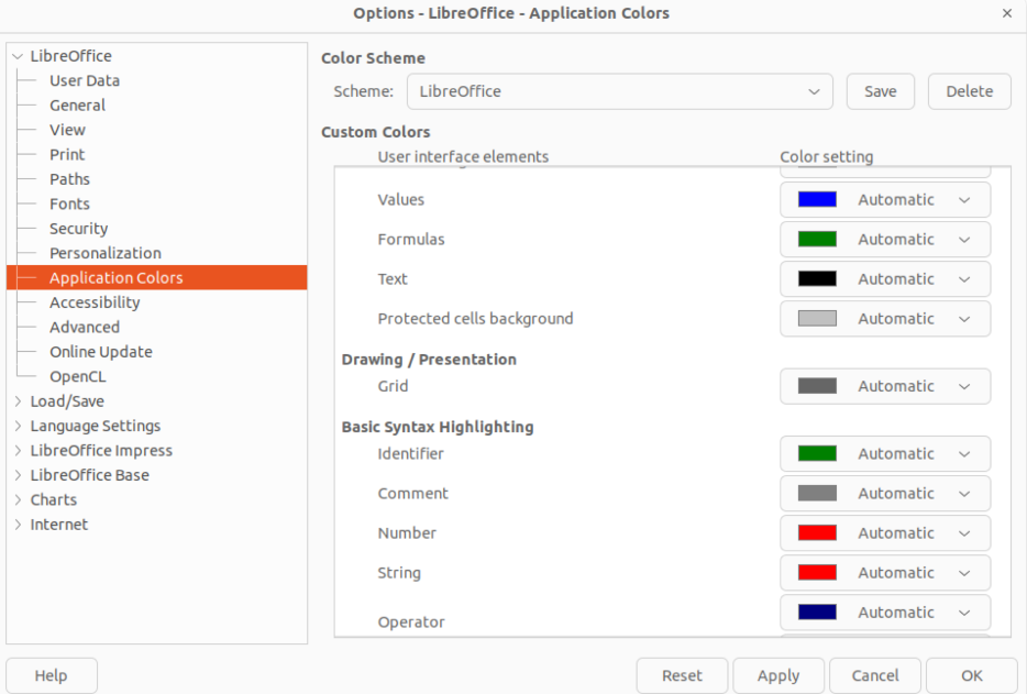
Figure 34: New Snap Object dialog
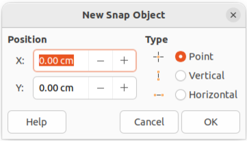
The options available in the New Snap Object dialog are as follows:
Position
X:
Enter the amount of space required between the snap point or line and the left edge of the page.
Y:
Enter the amount of space required between the snap point or line and the top edge of the page.
Type
Point
Inserts a snap point. Both X: and Y: text boxes are active.
Vertical
Inserts a vertical snap line. Only X: text box is active.
Horizontal
Inserts a horizontal snap line. Only Y: text box is active.
Tip
When positioning snap lines, it is useful to display the rulers by selecting View > Rulers on the Menu bar. Click on the horizontal or vertical ruler and drag a snap line onto the slide.
Display or turn off snap points and lines in a presentation using one of the following methods:
Go to View > Snap Guides > Display Snap Guides on the Menu bar.
Click on Display Snap Guides on the Options toolbar.
Right-click on a slide and select Snap Guides > Display Snap Guides from the context menu.
1) Right-click on a snap point and select Edit Snap Point from the context menu to open the Edit Snap Point dialog (Figure 35).
2) Enter new X: and Y: coordinate settings for the snap point and click OK.
Figure 35: Edit Snap Point dialog
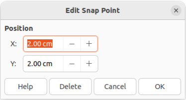
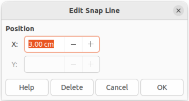
Figure 36: Edit Snap Line dialog
3) Alternatively, click on the snap point and drag it to a position on the slide.
1) Right-click on a snap line and select Edit Snap Line from the context menu to open the Edit Snap Line dialog (Figure 36).
2) Enter a new X: coordinate setting for vertical snap lines or a new Y: coordinate setting for horizontal snap lines and click OK.
3) Alternatively, click on a snap line and drag it to a new position on the slide.
1) Right-click on a snap point or line.
2) Select Delete Snap Point or Delete Snap Line from the context menu.
Note
Clicking on Delete in the Edit Snap Point dialog or Edit Snap Line dialog also deletes a snap point or snap line.
The default snap range of when an object snaps to a snap point or line can be configured as follows:
1) Go to Tools > Options > LibreOffice Impress > Grid (macOS LibreOffice > Preferences > LibreOffice Impress > Grid) on the Menu bar to open the Options LibreOffice Impress Grid dialog.
2) Enter the number of pixels to set the proximity of when the object snaps into position in the Snap range text box. The default setting is 5 pixels.
3) Click OK to set the new snap range and close the dialog.
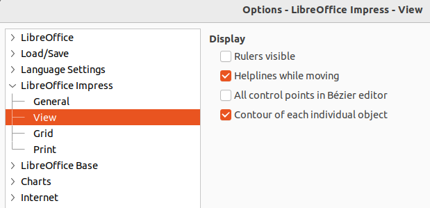
Helplines are a function in Impress to help position objects and can be displayed while an object is being moved. They extend from the edges of the object to the rulers at the top and left side of a workspace and do not have a snap function (Figure 37).
Use one of the following methods to display helplines while moving an object:
Go to Tools > Options > LibreOffice Impress > View (macOS LibreOffice > Preferences > LibreOffice Impress > View) to open the Options LibreOffice Impress View dialog (Figure 38) on the Menu bar and select Helplines while moving.
Click on Helplines While Moving on the Options toolbar.
Right-click in an empty area on a slide and select Grid and Helplines > Helplines While Moving from the context menu.
Figure 37: Example of using helplines
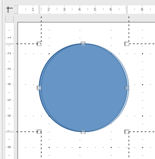
Figure 38: Options LibreOffice Impress View dialog
Impress organizes objects in a stack so that the objects on the top level of the stack cover the objects on lower levels, if any overlapping occurs. The stack level of each object can be changed by arranging shapes on a slide. Select an object or objects and use one of the following methods to change the stack level:
Click on the required arrange tool on the Line and Filling toolbar.
Right-click on selected objects and select Arrange from the context menu, then select the required arrange option from the sub-context menu.
Go to Format > Arrange on the Menu bar and select an option from the submenu.
The options available for arranging the object stack level on a slide are as follows:
Bring to Front
Bring Forward
Send Backward
Send to Back
In Front of Object
Behind Object
Reverse
Connectors are lines that can be anchored to gluepoints and by default are positioned on the border of an object. When an object with a connector attached is moved or resized, the connector automatically adjusts to the change. When creating a flowchart, organization chart, schematics, or diagrams, it is highly recommended to use connectors instead of simple lines.
When a connector is drawn or selected, Impress displays selection handles that are different to the selection handles for normal lines. The termination points of a connector are round at each end of a connector. The square selection handles on a connector line are used to change the routing of a connector where applicable.
Figure 39: Connectors sub-toolbar
Impress offers a wide variety of predefined connectors, which differ in the termination shape (none, arrow, circle) and in the way the connector is drawn (straight, line, curved). The connector types that are installed on the Connectors sub-toolbar (Figure 39) are normally indicated by a check mark or highlighting, depending on the computer operating system and setup.
The full list of available connector types that can be installed on the Connectors sub-toolbar are as follows. The connector types are numbered to indicate the installation position from left to right on the sub‑toolbar.
1) Connector Ends with Arrow
2) Straight Connector Ends with Arrow
3) Curved Connector Ends with Arrow
4) Line Connector Ends with Arrow
5) Connector
6) Straight Connector
7) Curved Connector
8) Line Connector
9) Connector with Arrows
10) Straight Connector with Arrows
11) Curved Connector with Arrows
12) Line Connector with Arrows
13) Connector Starts with Arrow
14) Straight Connector Starts with Arrow
15) Curved Connector Starts with Arrow
16) Line Connector Starts with Arrow
17) Connector Ends with Circle
18) Straight Connector Ends with Circle
19) Line Connector Ends with Circle
20) Curved Connector Ends with Circle
21) Connector Starts with Circle
22) Straight Connector Starts with Circle
23) Line Connector Starts with Circle
24) Curved Connector Starts with Circle
25) Connector with Circles
26) Straight Connector with Circles
27) Line Connector with Circles
28) Curved Connector with Circles
The full range of predefined connectors can be accessed by clicking on the triangle ▼ on the title bar of the Connectors sub-toolbar and selecting Visible Buttons. The connectors fall into four group as follows:
Standard
Line
Straight
Curved
1) Click on the triangle ▼ next to Connectors on the Drawing toolbar to open the Connectors sub-toolbar.
2) Select the type of connector required from the Connectors sub-toolbar.
3) Move the cursor over one of the objects to be connected and small crosses appear around the object edges, normally in the same position as selection handles. These crosses are gluepoints to which a connector attaches, as shown in Figure 40.
4) Click on the required gluepoint to attach one end of the connector, then click, hold and drag the connector to another object.
5) When the cursor is over the gluepoint of the target object release the cursor and the connector is drawn.
6) The selection handles that appear on the connector are used to adjust the path of the connector so that the connector can be adjusted not to cover another object in its path, as shown by the example in Figure 41.
Note
The ends of the connector cannot be swapped, that is start point cannot become the end point and the end point cannot become the start point. To swap the ends of a connector, a new connector has to be created in the opposite direction.
Figure 40: Example of connector gluepoints
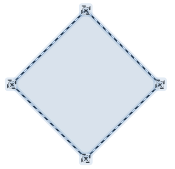
Figure 41: Example of connectors between objects
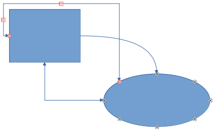
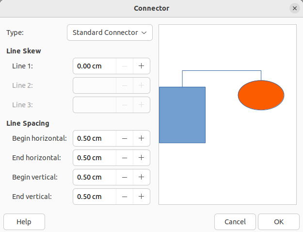
Figure 42: Connector dialog
To detach or reposition a connector, click on a round selection handle at either end of the connector and drag to a different location, as shown in Figure 41.
To change the connector route between objects avoiding any objects on the route, click on a square control handle on the connector line and drag it to a new position, as shown in Figure 41.
To change a connector type, right-click on the connector and select Connector from the context menu to open the Connector dialog (Figure 42). Use this dialog to select a connector type and change the connector properties.
Type
Select the connector type from the drop-down list.
Line skew
Line spacing
Begin horizontal
Amount of horizontal space required at the beginning of the connector.
Begin vertical
Amount of vertical space required at the beginning of the connector.
End horizontal
Amount of horizontal space required at the end of the connector.
End vertical
Amount of vertical space required at the end of the connector.
Preview window
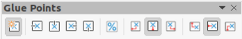
Figure 43: Gluepoints toolbar
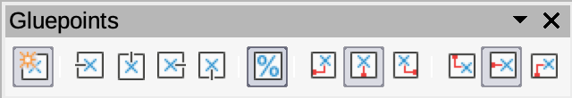
Glue points are not the same as the selection handles of an object. The selection handles are for moving or changing the shape of an object. Glue points are used to fix or glue a connector to an object so that when the object moves, the connector stays fixed to that object. All objects have gluepoints, which are not normally displayed and only become visible when Connectors on the Drawing toolbar is selected.
To insert, customize or delete gluepoints on an object, open the Gluepoints toolbar (Figure 43) using one of the following methods:
Go to View > Toolbars > Gluepoints on the Menu bar.
Go to Edit > Gluepoints on the Menu bar.
Click on Show Gluepoint Functions on the Drawing toolbar.
When the Gluepoints toolbar opens, only the six tools on the left of the toolbar are active. The remaining six tools on the right of the toolbar only become active when Gluepoint Relative is deselected.
The six tools on the left of the Gluepoints toolbar are as follows:
Insert Gluepoint
Exit Direction Left
Exit Direction Top
Exit Direction Right
Exit Direction Bottom
Gluepoint Relative
The six tools on the right of the Gluepoints toolbar only become active when Gluepoint Relative is deselected.
Gluepoint Horizontal Left
Gluepoint Horizontal Center
Gluepoint Horizontal Right
Gluepoint Vertical Top
Gluepoint Vertical Center
Gluepoint Vertical Bottom
Note
Glue points inserted into an object can only have one horizontal position and one vertical position. Only one horizontal position and/or one vertical position can be selected on the Gluepoints toolbar and used to customize a gluepoint.
By default, most objects normally have four gluepoints. Insert additional gluepoints into an object as follows:
1) Make sure no objects are selected and use one of the following methods to open the Gluepoints toolbar:
Go to View > Toolbars > Gluepoints on the Menu bar.
Go to Edit > Gluepoints on the Menu bar.
Click on Show Gluepoint Functions on the Drawing toolbar.
2) Select the object, then click on Insert Gluepoint on the Gluepoints toolbar. Alternatively, right-click on a gluepoint previously inserted and select Insert Gluepoint from the context menu.
3) Move the cursor to a position where the gluepoint is to be inserted into an object and click to insert the gluepoint.
4) To insert more gluepoints, move the cursor to a new position and click to insert another gluepoint.
5) With the gluepoint selected, select the type of gluepoint required from the options on the Gluepoints toolbar.
6) To move a gluepoint to another position, click on the gluepoint and drag it to its new position.
7) When inserting gluepoints is complete, make sure Insert Gluepoint on the Gluepoints toolbar is deselected.
Tip
When inserting, moving or customizing gluepoints, it is recommended to use the zoom function to make it easier to work with gluepoints. Also, gluepoints snap to the grid making it easier to position a gluepoint.
Note
Only gluepoints that have been inserted onto an object can be customized or deleted. The default gluepoints included with an object cannot be customized or deleted.
1) Make sure no objects are selected and use one of the following methods to open the Gluepoints toolbar:
Go to View > Toolbars > Gluepoints on the Menu bar.
Go to Edit > Gluepoints on the Menu bar.
Click on Show Gluepoint Functions on the Drawing toolbar.
2) Double-click on a gluepoint that has been inserted to select the gluepoint for customization.
3) Select an exit direction for the connector from the options available on the Gluepoints toolbar, or right-click on the gluepoint and select the exit direction from the context menu.
4) When customizing exit direction is complete, make sure Insert Gluepoint on the Gluepoints toolbar is deselected.
1) Make sure no objects are selected and use one of the following methods to open the Gluepoints toolbar:
Go to View > Toolbars > Gluepoints on the Menu bar.
Go to Edit > Gluepoints on the Menu bar.
Click on Show Gluepoint Functions on the Drawing toolbar.
2) Double-click on a gluepoint that has been inserted to select the gluepoint for customization.
3) Click on Gluepoint Relative on the Gluepoints toolbar to deselect this tool, or right-click on the gluepoint and deselect Gluepoint Relative from the context menu.
4) Select the horizontal and vertical positioning tools required for the gluepoint. Only one horizontal positioning tool and one vertical positioning tool can be used on a gluepoint at any one time.
5) When customizing gluepoint position is complete, make sure Insert Gluepoint on the Gluepoints toolbar is deselected.
1) Make sure no objects are selected and use one of the following methods to open the Gluepoints toolbar:
Go to View > Toolbars > Gluepoints on the Menu bar.
Go to Edit > Gluepoints on the Menu bar.
Click on Show Gluepoint Functions on the Drawing toolbar.
2) Select the gluepoint that has been previously inserted.
3) Press the Delete, or Backspace key, or go to Edit > Cut on the Menu bar.
Although Impress offers advanced functions to manipulate 3D objects, this guide describes only the 3D settings applicable to an object. For additional information on how to use advanced 3D effects such as geometry and shading, refer to the Draw Guide.
3D objects can be created in Impress in any of the following ways:
Click on the triangle ▼ next to 3D Objects on the Drawing toolbar and select a 3D object from the drop-down list. After selection, draw a 3D object in exactly the same way as any other object. The icon shown on the Drawing toolbar depends on the 3D object that had been previously selected and used.
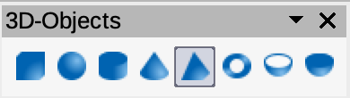
Go to View > Toolbars > 3D-Objects on the Menu bar to open the 3D-Objects toolbar (Figure 44). This toolbar is the same as the 3D-Objects sub-toolbar that is available on the Drawing toolbar.
Figure 44: 3D-Objects toolbar
Right-click on an object already drawn on a slide and select Convert > To 3D or To 3D Rotation Object from the context menu. To 3D adds thickness to the object to create a 3D object. To 3D Rotation Object creates a 3D object by rotating the object around an axis.
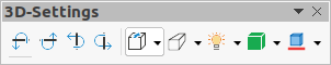
Select an object and click on Toggle Extrusion on the Drawing toolbar to apply a basic 3D effect and open the 3D-Settings toolbar (Figure 45). Select one of the options on the 3D-Settings toolbar to apply a different 3D effect.
Figure 45: 3D-Settings toolbar
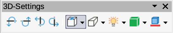
The options available on the 3D‑Settings toolbar are as follows:
Toggle Extrusion
Tilt Down
Tilt Up
Tilt Left
Tilt Right
Depth
Direction
Lighting
Surface
3D–Color
Note
Most of the Fontwork shapes (see “Fontwork” on page 1) have 3D properties and can be manipulated with the 3D-Settings toolbar.
Objects are converted into different types using one of the following methods:
Right-click on the object and select Convert from the context menu, then select a conversion option from the context menu.
Select an object and go to Format > Convert on the Menu bar and select a conversion option from the submenu.
To Curve
To Polygon
To Contour
To 3–D
To 3–D Rotation Object
To Bitmap
To Metafile
Note
In most cases the conversion to a different type of object does not immediately produce visible results.
Tip
To Curve, To Polygon, To 3–D, and To 3–D Rotation Object can be added to the Drawing toolbar as additional tools by right-clicking in an empty area on the toolbar and selecting Visible Buttons. See Appendix B, Toolbars for more information.
Associating an object to an action that is performed when the object is clicked is called an interaction.
1) Select an object for interaction and open the Interaction dialog (Figure 46) using one of the following methods:
Click on Interaction on the Line and Filling toolbar.
Right-click on the object and select Interaction from the context menu.
Go to Format > Interaction on the Menu bar.
2) Select the interaction from the available options in Action at mouse click and any parameters (if applicable) that maybe available. The Interaction dialog changes depending on the type of interaction selected. The interactions and parameters are explained in Table 1.
3) Click OK to save the changes and close the dialog.
4) To remove an interaction from an object, repeat the procedure and select No action as the interaction type at Step 2.
Figure 46: Interaction dialog
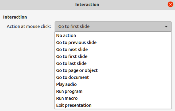
Table 1: Interaction types and parameters
|
Interaction |
Parameters |
|
No action |
No parameters. |
|
Go to previous slide |
No parameters. |
|
Go to next slide |
No parameters. |
|
Go to first slide |
No parameters. |
|
Go to last slide |
No parameters. |
|
Go to page or object |
Specify the target from the list in the Target box. Search for a specific target in the Slide/Object box at the bottom of the screen. |
|
Go to document |
Select the document in the Document box. Use Browse to open a file browser. If the document to be opened is in ODP format, the target list is populated allowing selection of the specific target. |
|
Play sound |
Select the file containing the sound to be played. Use Browse to open a file browser. |
|
Run program |
Select the program to execute. Use Browse to open a file browser. |
|
Run macro |
Select a macro that runs during the presentation. Use Browse to open the Macro Selector dialog. |
|
Exit presentation |
When the cursor is clicked over the object, the presentation terminates. |
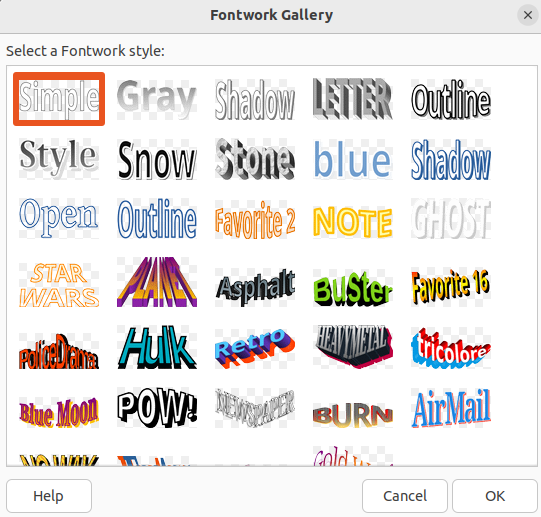
Figure 47: Fontwork Gallery dialog
With Fontwork, graphical text art objects can be created to make a presentation more attractive. There are many different settings for text art objects (line, area, position, size, and more) giving a large selection of effects. Fontwork is also available with the Writer, Calc, and Draw modules of LibreOffice, but there are small differences in the way that each module displays it. For more information about Fontwork, see the Getting Started Guide.
1) Click on Fontwork on the Standard toolbar, or go to Insert > Fontwork on the Menu bar to open the Fontwork Gallery dialog (Figure 47).
2) Select a Fontwork style from the dialog and click OK. The selected Fontwork appears centrally on the slide and the dialog closes.
3) Double-click on the Fontwork text graphic to switch on editing mode.
4) Type in the required text to replace the default text in the Fontwork graphic and the text appears over the default text as shown by the example in Figure 48.
5) Press the Esc key or click outside the Fontwork graphic and the text replaces default text.
The Fontwork toolbar (Figure 49) becomes visible and active when a Fontwork object is selected. If the toolbar is not visible, go to View > Toolbars > Fontwork on the Menu bar. Also, the Fontwork panel opens in the Properties deck on the Sidebar (Figure 50) and contains the same tools as the Fontwork toolbar.
Figure 48: Example of creating Fontwork

Figure 49: Fontwork toolbar
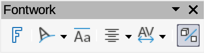
Figure 50: Fontwork panel in Properties deck on Sidebar
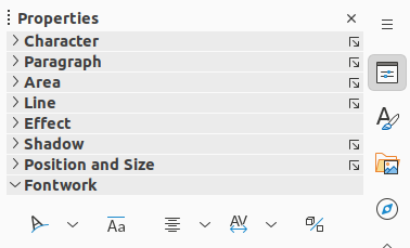
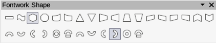
Figure 51: Fontwork Shape sub-toolbar
The Fontwork toolbar contains the following tools:
Insert Fontwork Text
Fontwork Shape
Fontwork Same Letter Heights
Fontwork Alignment
Fontwork Character Spacing
Toggle Extrusion
It is possible to treat Fontwork text as an object and apply all the formatting that has been described in this chapter. Assign line properties only to Fontwork which does not have a 3D effect, otherwise the changes will not be visible. Also, modify some of the Fontwork shapes by moving the dot that is displayed along with the selection handles. This is similar to modification of the angles of trapezoid and parallelogram basic shapes.
Animated slide transitions can be added between slides to give presentations a more professional look when changing to the next slide (see Chapter 9, Slide Shows for more information on transitions). However, Impress also allows animations to be added onto the slides to create more interest in a presentation.
An animation consists of a sequence of images or objects called frames that are displayed in succession when the animation runs. Each frame may contain one or more objects. For example, bullet points appearing one by one; pictures, shapes or other objects appearing singly or as a group onto a slide. Animations can be controlled using the keyboard, a click, or automatically in a timed sequence.
Note
Anything that can be placed onto a slide is an object. For example, an object can be an image, clip art drawing, text, and so on.
Tip
Animations can look great in a presentation, but overuse of animations can make a good presentation into a poor presentation. Always use discretion when adding animations to a presentation.
1) Select an object on a slide and open the Animation deck on the Sidebar (Figure 52) using one of the following methods:
Click on Animation on the Sidebar.
Right-click on a selected object and select Animation from the context menu.
Go to View > Animation on the Menu bar.
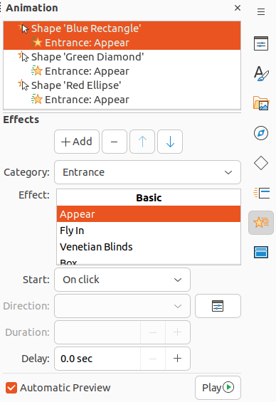
2) Click on Add Effect to add the selected object into the Animation preview box.
3) Select a category type from the options available in the Category drop-down list.
4) Select an animation effect from the options available in the Effects list.
5) Select how the animation starts from the options available in the Start drop-down list.
6) Select how the animation appears from the options available in the Direction drop-list. Available options are specific to the effect selected in the Effects list.
7) Enter a time in seconds for how long the animation lasts in the Duration box.
8) Enter a timing delay in seconds for when the animated object appears in the presentation in the Delay box.
Figure 52: Animation deck on Sidebar
9) If necessary, click on Options to open the Effect Options dialog (Figure 53 below) to set any effect options required for the animation, then click OK to close the Effect Options dialog.
10) If necessary, change the order of when the selected object appears in the animation using Move Up or Move Down below the Animation preview box.
11) Click on Play to preview the animation effect.
12) If necessary, select Automatic Preview so that each time the animation is changed, there is a preview of the effect.
13) When satisfied, run the slide show to check the presentation.
The available tools and options on the Animation deck on the Sidebar provides control over how an animation is applied to an object on a slide.
Add Effect
Remove Effect
Move Up
Move Down
Category
Effect
Start
On click
Animation stops at this effect until the next click.
With previous
Animation runs immediately.
After previous
Animation runs as soon as the previous animation ends.
Direction
Options
Duration
Delay
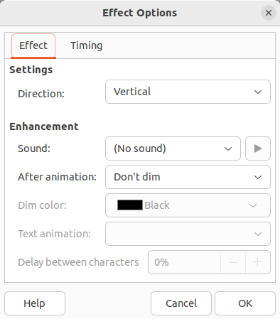
Figure 53: Effect Options dialog – Effect page
Automatic Preview
Play
The Effect page (Figure 53) contains options that match the animation effect selected:
Settings
Direction
Specify the direction of the animation effect from the options available in the drop-down list.
Enhancement
Sound
Select a sound from the drop-down list that plays when the animation effect is run.
After animation
Select from the drop-down list what happens after an animation effect ends.
— Don't dim – no after-effect runs.
— Dim with color – after the animation a dim color fills the shape.
— Hide after animation – hides the shape after the animation ends.
— Hide on next animation – hides the shape on the next animation.
Dim color
Select a dim color from the available color palettes.
Text animation
Select the animation mode for the text in an object:
— All at once – animates the text all at once.
— Word by word – animates the text word by word.
— Letter by letter – animates the text letter by letter.
Delay between characters
Specifies the percentage of delay between animations of words or letters.
The Timing page on the Effect Options dialog (Figure 54) contains the following options:
Timing
Start
Displays the start property of the selected animation effect.
— On click – animation stops at this effect until the next click.
— With previous – animation runs immediately.
— After previous – animation runs as soon as the previous animation ends.
Delay
Specifies a delay in seconds before the effect starts.
Duration
Specifies the duration in seconds of the effect.
Figure 54: Effect Options dialog - Timing page
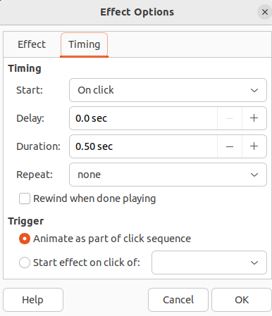
Repeat
Specifies whether and how to repeat the current effect. Enter the number of repeats, or select from the list:
— none – effect is not repeated.
— Until next click – animation is repeated until the next click.
— Until end of slide – animation repeats as long as the slide is displayed.
Rewind when done playing
Specifies whether to let the animated object returns to its starting state after the animation ends.
Trigger
Animate as part of click sequence
Specifies whether to let the animation start in the normal click sequence.
Start effect on click of
Specifies whether to let the animation start when a specified shape is clicked. Select the shape by its name from the drop-down list.
The Text Animation page on the Effect Options dialog (Figure 55) contains the following options:
Group text
As one object
Whole text object is animated.
All paragraphs at once
All text paragraphs are animated.
By XX level paragraphs
Text for the outline level selected is animated. The options available depends on how many outline levels there are in the animated text.
Figure 55: Effect Options dialog - Text Animation page
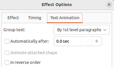
Automatically after
Animate attached shape
In reverse order
Animation of drawing objects, text objects, and graphic objects (images) on slides can make a presentation more interesting. LibreOffice Impress provides a simple animation editor where animation images (frames) can be created by assembling objects from a slide. The animation effect is achieved by rotating through static frames that are created.
The following is an example of how to create an animated image.
1) Select an object or group of objects for inclusion in an animation and go to Insert > Media > Animated Image to open the Animation dialog (Figure 56).
Figure 56: Animation dialog
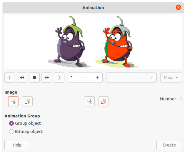
2) Add an object or objects using one of the following methods:
Click on Apply Object to add a single object or a group of objects to the current animation frame.
Click on Apply Objects Individually to create a separate animation frame for each of the selected objects.
3) In Animation Group, select Bitmap object.
4) Enter the frame (image) number in the Image Number box to setup the image.
5) In Duration specify the duration time in seconds for displaying a frame.
6) Specify the number of times a frame is displayed in the animation sequence in Loop Count. This is called looping.
7) Repeat Steps 4 thru 6 for each image or object used for the animated image.
8) Click on Create and the animated image appears centrally on the slide.
Note
If the image to be copied consists of several objects, each object can be treated as a separate frame. In this case, click on Apply Objects Individually. Remember that each object is centered in the animation.
First Image
Backwards
Stop
Play
Last Image
Image Number
Duration
Loop Count
Apply Object
Apply Objects Individually
Delete Current Image
Delete All Images
Number
Group object
Bitmap object
Create
Note
An animation, such as an animated GIF, can be selected. Click Apply Objects Individually to open it for editing. When finished editing the animation, click Create to insert a new animation into a slide.