
Impress Guide 7.3
Chapter 6,
Formatting Graphic Objects
This document is Copyright © 2022 by the LibreOffice Documentation Team. Contributors are listed below. This document maybe distributed and/or modified under the terms of either the GNU General Public License (https://www.gnu.org/licenses/gpl.html), version 3 or later, or the Creative Commons Attribution License (https://creativecommons.org/licenses/by/4.0/), version 4.0 or later.
All trademarks within this guide belong to their legitimate owners.
|
Peter Schofield |
Kees Kriek |
|
|
Peter Schofield |
Samantha Hamilton |
Michele Zarri |
|
T. Elliot Turner |
Jean Hollis Weber |
Vasudev Narayanan |
|
Rachel Kartch |
|
|
Please direct any comments or suggestions about this document to the Documentation Team’s mailing list: documentation@global.libreoffice.org
Note
Everything sent to a mailing list, including email addresses and any other personal information that is written in the message, is publicly archived and cannot be deleted.
Published May 2022. Based on LibreOffice 7.3 Community.
Other versions of LibreOffice may differ in appearance and functionality.
Some keystrokes and menu items are different on macOS from those used in Windows and Linux. The table below gives some common substitutions for the instructions in this document. For a detailed list, see the application Help.
|
Windows or Linux |
macOS equivalent |
Effect |
|
Tools > Options on Menu bar |
LibreOffice > Preferences on Menu bar |
Access to setup options |
|
Right-click |
Ctrl+click and/or right-click depending on computer setup |
Opens a context menu |
|
Ctrl or Control |
⌘ and/or Cmd or Command |
|
|
Alt |
⌥ and/or Alt or Option |
Used with other keys |
|
F11 |
⌘+T |
Open the Styles deck in the Sidebar |
The format of each graphic object, in addition to its size, rotation, and position on the slide, is determined by a number of attributes that define the line, text, and area fill of each object. These attributes (among others) also contribute to a graphics style. Although this chapter discusses mainly the manual formatting of objects, it concludes by showing how to create, apply, modify, and delete graphics styles.
Note
When hovering the cursor over an icon or tool on a toolbar or in the Sidebar, pop-up text indicates the purpose of the icon or tool.
In LibreOffice the term line indicates both a freestanding segment (line), the outer edge of a shape (border), or an arrow. In most cases, the properties of the line that can be modified are style (solid, dashed, invisible, and so on), width, color, and type of arrowhead.
Note
When adding color to a line or arrow, refer to “Color fills” on page 1 on how to change color, create custom colors, modify colors, or delete colors.
Format a line using the Line and Filling toolbar (Figure 1) as follows:
1) Make sure a line is selected on a slide.
2) Select a line style from the Line Style drop-down list.
3) Either type the line width in the Line Width text box, or use the up and down arrows to change the line width.
4) Click on the triangle ▼ to the right of Line Color and select a color from one of the color palettes that are available.
5) If necessary, select from the Arrow Style drop-down list the type of arrowhead for each end of the line and change the line into an arrow. The left drop-down list adds an arrow head to the beginning of the line. The right drop-down list adds an arrow head to the end of the line.
6) If necessary, click on Shadow to add a shadow to the line. The shadow applied uses the settings set in the Line dialog (Figure 6 on page 1).
7) Deselect the line to save the changes to the line.
Figure 1: Line and Filling toolbar

Figure 2: Line panel in Properties deck on Sidebar
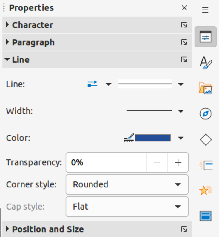
To format a line using the Line panel in the Properties deck on the Sidebar (Figure 2):
1) Make sure a line is selected on a slide.
2) Click on Properties on the Sidebar to open the Properties deck.
3) Click on Line to open the Line panel.
4) In Line when an arrow is being created, select from the Arrow Style drop-down list the type of arrowhead for each end of the line and change the line into an arrow. The left drop-down list adds an arrow head to the beginning of the line. The right drop-down list adds an arrow head to the end of the line.
5) In Line, select from the Line Style drop-down list the type of line from the options available.
6) In Width, select a line width from the options in Select the width of the line drop-down list or enter a width in the Custom Line Width text box.
7) In Color, select a line color from one of the color palettes that are available in the Line Color drop-down list.
8) In Transparency, move the slider or enter a percentage in the text box to set the shadow transparency.
9) In Corner style, select a corner style from the options available in the drop‑down list.
10) In Cap style, select the style of the line end caps from the drop-down list. The cap style is added to dashes also if dashes have been used in the line style.
11) Deselect the line to save the changes to the line.
12) If necessary, click on More Options on the right of the title bar and open the Line dialog for more control over formatting lines.
Figure 3: Line dialog - Line page
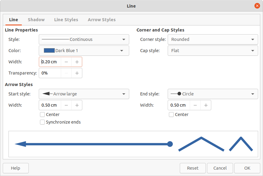
To fully change the appearance of a line, then the Line dialog is used. The line dialog consists of four pages: Line, Shadow, Line Styles and Arrow Styles, which are explained in the following sections.
1) Make sure a line is selected on a slide.
2) Open the Line dialog (Figure 3) using one of the following methods:
Go to Format > Object and Shape > Line on the Menu bar.
Right-click on the line and select Line from the context menu.
Click on More Options on the right of the Line panel title bar in the Properties deck on the Sidebar.
3) When all changes have been made to the selected line, click OK to close the dialog and save the changes. The preview box at the bottom of the dialog shows the effect of any changes made to a line.
The Line page in the Line dialog (Figure 3) is where the basic parameters of a line are selected and are as follows:
Line Properties – this section is used to set the following parameters:
Style – select a line style from the Style drop-down list.
Color – select a predefined color from the available color palettes. To create a custom color, see to “Color fills” on page 1 for more information.
Width – specifies the thickness of the line.
Figure 4: Example of line transparency (0%, 25%, 50%, 75% left to right)
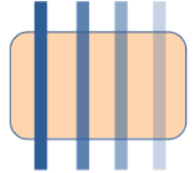
Transparency – sets the transparency percentage of a line. Figure 4 is an example of the effect different transparency percentages have when lines placed over an object.
Arrow Styles – this section is only applicable to individual lines and is not used for lines that form the borders of an object.
Start Style – select the arrow style for the start of a line from the drop-down list.
Width – specifies the thickness of the start arrow ending.
End Style – select the arrow style for the end of a line from the drop-down list.
Width – specifies the thickness of the end arrow ending.
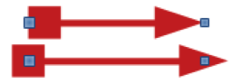
Center – moves the center of the arrow endings to the end point of the line. Figure 5 is an example of the effects of selecting this option.
Synchronize ends – makes the two line ends identical.
Figure 5: Example of default (top) and center (bottom) arrow heads
Corner and Cap Styles – determines how the connection between two segments of a line looks. To appreciate the difference between corner and cap styles, choose a thick line style and observe how the preview changes as each option is selected.
Corner style – select the shape used at the corners of the line from the drop-down list. For a small angle between lines, a mitered shape is replaced with a beveled shape.
Cap style – select the style of the line end caps from the drop-down list. The caps are added to inner dashes as well.
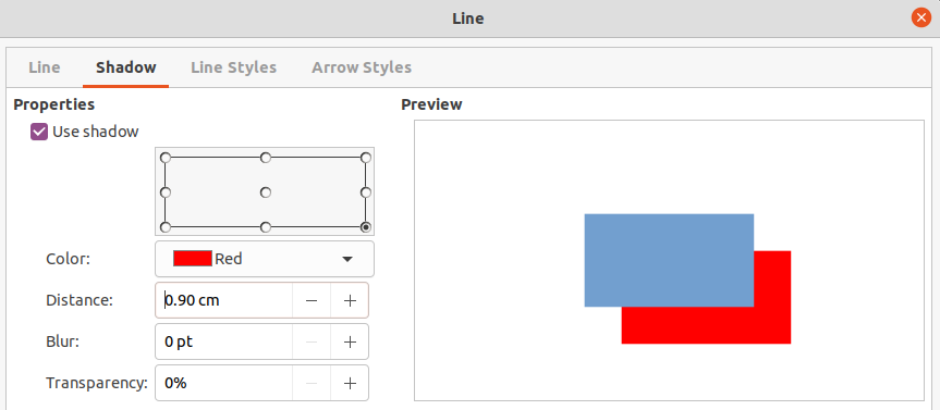
The Shadow page (Figure 6) of the Line dialog provides options to add and format a line shadow. The shadow settings in this dialog are the same as the shadow settings in the Area dialog (Figure 27 on page 1). However, shadow settings in the Line dialog can have different values than the shadow settings in the Area dialog. For more information on shadow settings, see “Working with shadows” on page 1.
Figure 6: Line dialog - Shadow page
To quickly apply a shadow to a line, click on Shadow on the Line and Filling toolbar. Using the Shadow tool creates a shadow using the settings from the Shadow page in the Line dialog.
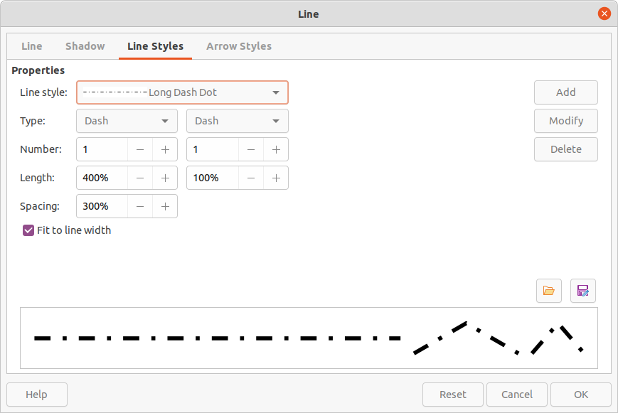
Line styles are useful in a drawing when adding several lines of similar types. This reduces the need to format individual lines. LibreOffice provides standard line styles that can be used in a drawing. Also, line styles can be created, saved, and deleted.
The Line Styles page in the Line dialog (Figure 7) provides the options to use predefined line styles and to create or change line styles. An example of the line style selected or created is displayed at the bottom of the Line Styles page.
1) Create a line in a drawing.
2) Open the Line dialog using one of the following methods:
Go to Format > Object and Shape > Line on the Menu bar.
Right-click on the line and select Line from the context menu.
3) Click on Line Styles to open the Line Styles page.
4) Select from the Line style drop-down menu a predefined line style that is similar to the line style being created.
5) Click Add and type a name for the new line style in the Name dialog that opens, then click OK to close the dialog. The name of the new style appears in the Line style box.
6) In the Type drop-down lists, select Dots or Dash. For lines with only dots or dashes, select the same type in both Type boxes.
7) In Number, specify the number of dots or dashes required. For different sized groups of dots or dashes, set a different quantity number in each Number box.
8) In Length, specify the length percentage for dashes. Length is not available if Dots has been selected for Type.
9) In Spacing, set a spacing percentage between the dots and/or dashes.
10) If necessary, select Fit to line width so that the new style fits the width of the selected line.
Figure 7: Line dialog - Line Styles page
11) The new line style created is available only in the current document. To use the new line style in other documents, click on Save Line Styles and type a unique filename in the Save as dialog that opens. Saved line styles have the file extension of.sod.
12) To use a previously created line style, click on Load Line Styles, then select a style from the list of saved styles and click on Open to load the style into the document.
13) If necessary, click on Modify to change the name of the style and follow Steps 4 thru 11 to create and use a new line style.
14) Click OK to save any changes and close the Line dialog.
Note
When creating a line style, it is recommended to use a unique name for the line style. This prevents one of the predefined line styles in LibreOffice from being overwritten and causing formatting problems in other documents that use the predefined line styles.
1) Open the Line dialog and click on Line Styles to open the Line Styles page.
2) Select the line style for deletion from the Line style drop-down list.
3) Click on Delete, then confirm the deletion by clicking on Yes in the confirmation dialog that opens.
4) Click OK to save any changes and close the Line dialog.
Note
When deleting line styles, make sure that the line style is not used in another document. It is recommended to only delete line styles that have been created and not to delete one of the LibreOffice predefined line styles. This prevents any formatting problems in other documents where the line style has been used.
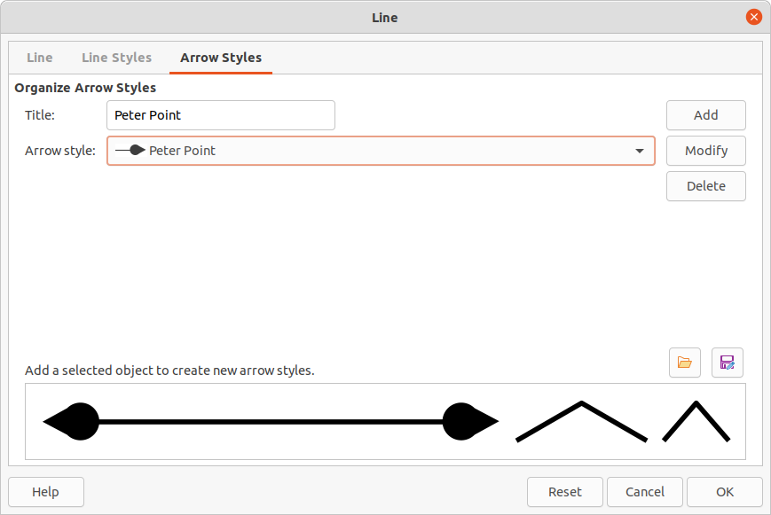
Any shape can be used as an arrowhead, but the shape must be convertible to a curve. A curve is something drawn without lifting a pencil. For example, a star can be converted to a curve, but a smiley face cannot.
1) Select a shape, or create a shape that can be converted to a curve for use as a new arrowhead. The part of the shape that is going to be point of the arrowhead must face upward. An example of a new arrowhead is shown in Figure 8.
2) If necessary, select the shape, right-click and select Convert > To Curve from the context menu. If the shape is already a curve, To Curve will not be available.
3) Make sure the arrowhead shape is selected.
4) Open the Line dialog and click on Arrow Styles to open the Arrow Styles page (Figure 9).
5) Click on Add, type a name for the new arrow style in the dialog that opens, then click OK. The new arrowhead style appears on the Arrow Styles page and at the bottom of the Arrow style drop-down list.
6) The new arrow style created is available only in the current document. To use the created arrow style in other documents, click on Save arrow styles and type a unique filename in the dialog that opens. Saved arrow styles have the file extension of .soe.
7) To use a previously saved arrow styles, click on Load arrow styles to open a file browser and select the style from the saved list of styles. Click Open to load the style into a document.
Figure 8: Example of a shape being used for a arrowhead

Figure 9: Line dialog - Arrow Styles page
8) If necessary, make changes to the arrow style and click on Modify, then enter a name in the dialog to change the name of the arrow style.
9) Click OK to save any changes and close the Line dialog.
1) Open the Line dialog using one of the following methods:
Go to Format > Object and Shape > Line on the Menu bar.
Right-click on the line and select Line from the context menu.
2) Click on Arrow Styles to open the Arrow Styles page.
3) Select the arrow style for deletion from the Arrow style drop-down list.
4) Click on Delete, then confirm the deletion by clicking on Yes in the confirmation dialog that opens.
5) Click OK to save any changes and close the Line dialog.
Note
When deleting arrow styles, make sure that the arrow style is not used in another document. It is recommended to only delete arrow styles that have been created and not to delete one of the LibreOffice predefined arrow styles. This prevents any formatting problems in other documents where the arrow style has been used.
Figure 10: Examples of area fill types
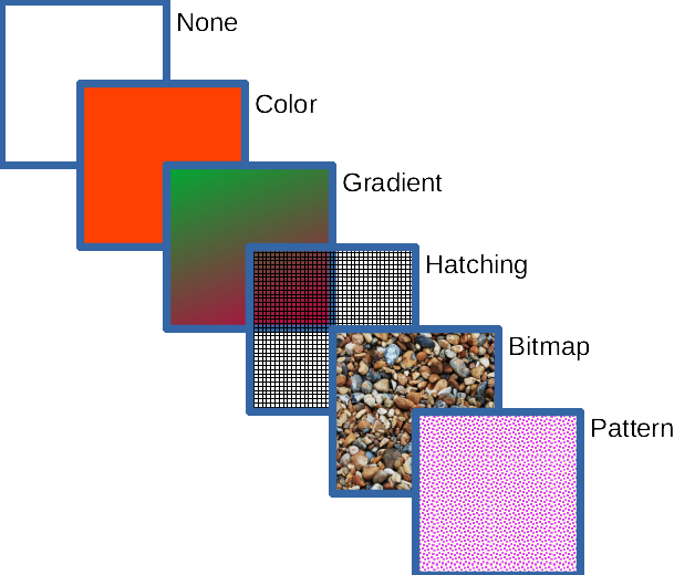
Area fill refers to the inside of an object that has an unbroken border, for example a rectangle, circle, star, pentagon and so on. An area fill can be a uniform color, gradient, hatching pattern, or bitmap, as shown by the examples in Figure 10. An area fill can also be made partly or wholly transparent and throw a shadow. For more information on area fills, see “Working with area fills” on page 1.
Tools on the Line and Filling toolbar provide a wide number of default fillings available to quickly format graphic objects. If this toolbar is not showing, go to View > Toolbars > Line and Filling on the Menu bar.
1) Select an object so that the selection handles are displayed.
2) From the Area Style/Filling drop-down list on the Line and Filling toolbar, select the type of fill required.
None – select this option if an area fill for an object is not required.
Color (Figure 11) – select a color palette from the available options in the drop-down list, then select a color by clicking on the color.
Gradient (Figure 12) – select the required gradient from the drop-down list.
Hatching (Figure 13) – select the required hatching from the drop-down list.
Bitmap (Figure 14) – select the required bitmap from the drop-down list.
Pattern (Figure 15) – select the required pattern from the drop-down list.
3) Deselect the object to save any changes.
Figure 11: Color area fills
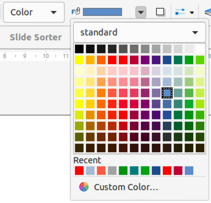
Figure 12: Gradient area fills
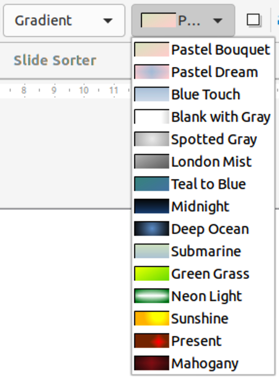
Figure 13: Hatching area fills
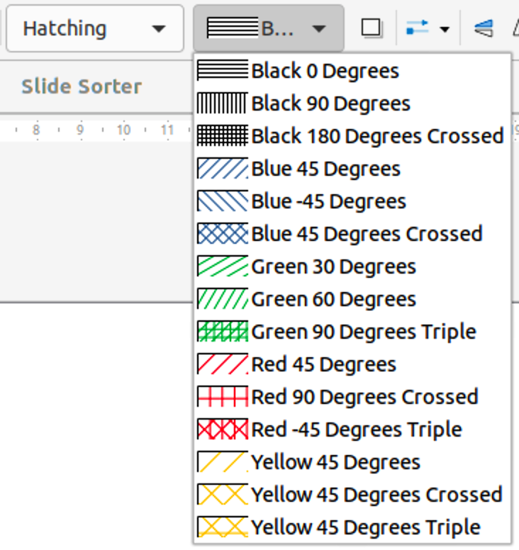
Figure 14: Bitmap area fills
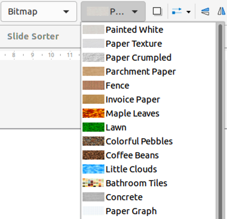
Figure 15: Pattern area fills
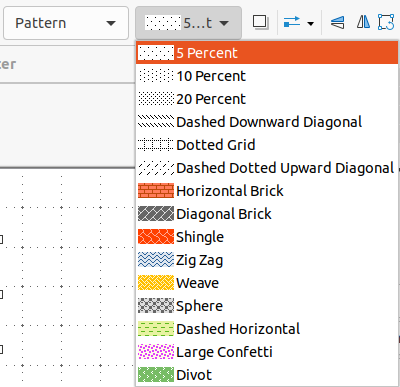
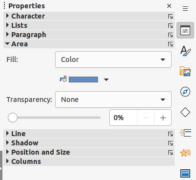
Figure 16: Area panel in Properties deck on Sidebar
1) Select an object for editing.
2) Click on Properties on the Sidebar to open the Properties deck, then click on Area to open the Area panel (Figure 16).
3) Use the various options in the Fill and Transparency drop-down lists to format the fill and transparency of an object. For more information on area fills, see “Working with area fills” on page 1.
4) Deselect the object to save any changes.
5) If necessary, click on More Options on the right of the Area title bar to open the Area dialog giving more control over the appearance of the object fill.
Note
The area fills available in the Fill drop-down list are the same as the drop-down lists available on the Line and Filling toolbar and shown in Figures 11 thru 15.
Note
If an area fill for an object is not required, select None from the Fill drop‑down list in the Area panel in the Properties deck on the Sidebar.
Use the Area dialog (Figure 17) to change existing area fills with greater control or create an area fill.
1) Select an object for editing.
2) Open the Area dialog using one of the following methods:
Go to Format > Object and Shape > Area on the Menu bar.
Right-click on the object and select Area from the context menu.
Click on More Options on the right of the Area panel title on the Sidebar.
Figure 17: Area dialog - Area Color page
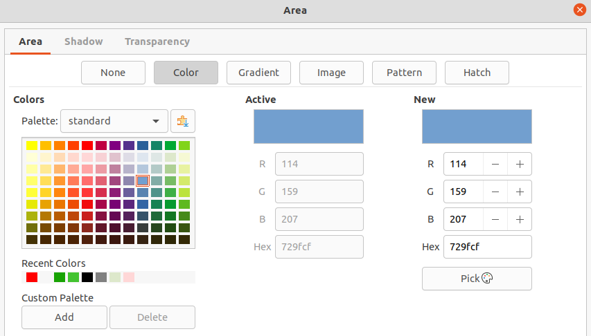
3) Click on Area to open the Area page.
4) Select the type of area fill from the options available: None, Color, Bitmap, Gradient, Pattern, or Hatch. For more information on area fills, see “Working with area fills” below.
5) Select the style of area fill from the options that become available. The number of available options depends on the type of area fill selected.
6) Click OK to close the Area dialog and save the changes.
Note
If an area fill for an object is not required, select None from the options available after opening the Area page in the Area dialog.
Although the characteristics of an existing area fill can be changed and then modified by clicking the Modify button, it is recommended that only custom area fills are modified rather than modifying the predefined area fills supplied with LibreOffice. Predefined area fills may be reset when LibreOffice is updated
1) Select an object for editing.
2) Open the Area dialog and click on Area to open the Area page, then click on Color to open the options available for a color fill (Figure 17).
3) In Palette, select the required color palette from the drop-down list and the required color from the available colors shown. All color fills available are solid colors.
Active – shows the present color fill of a selected object. After selecting a new color, a preview of the selected color appears in New.
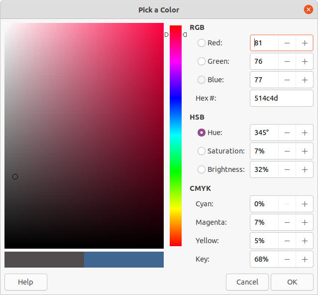
Figure 18: Pick a Color dialog
Alternatively, enter the RGB or Hex values of a color in the appropriate text box.
Alternatively, click on Pick to open the Pick a Color dialog (Figure 18). Select a color from the color box or enter the RGB, Hex, HSB or CMYK values for the color required.
If a color has been used before, then select the required color from those available in Recent Colors.
4) Click OK to close the dialog and save the changes. The area fill appears in the selected object.
Custom colors can be created either as a combination of the three primary colors using RGB notation of Red (R), Green (G), and Blue (B) or using CMYK percentages of Cyan (C), Magenta (M), Yellow (Y), and Black (K).
1) Select an object for editing.
2) Open the Area dialog and click on Area to open the Area page, then click on Color to open the options available for a color fill.
3) Specify the Red (R), Green (G), and Blue (B) values on a 0 to 255 scale to create a new color.
4) Click on Add in Custom Palette and enter a name in the Name dialog that opens.
5) Click OK to close the Name dialog and the color is added to the Custom palette.
6) Click OK to save the changes and close the Area dialog. The new color appears as a fill in the selected object.
1) Select an object for editing.
2) Open the Area dialog and click on Area to open the Area page, then click on Color to open the options available for a color fill.
3) Click on Pick to open the Pick a Color dialog (Figure 18).
4) Create a new color using one of the following methods. A preview of the color created is shown in the colored box below the original color on the left side of the dialog.
Select a color range from the colored bar, then, using the cursor, move the target in the colored box until the cursor is on the color required.
Enter values for Red (R), Green (G), and Blue (B) in the RGB text boxes.
Enter values for Cyan (C), Magenta (M), Yellow (Y), and Key (K) (black) in the CMYK text boxes.
Enter values for Hue (H), Saturation (S), and Brightness (B) in the HSB text boxes. HSB values do not change the color, but how a color looks.
If known, enter the Hex# number in the text box. For example, Hex numbers are normally used when a specific color has been created, for example a company logo.
Note
Changing one set of color values automatically changes the values in the other sets of color values.
5) Click OK to close the Pick a Color dialog.
6) Click on Add in Custom Palette and enter a name for the color in the Name dialog that opens.
7) Click OK to close the Name dialog and the color is added to the Custom palette.
8) Click OK to save the changes and close the Area dialog. The new color appears as a fill in the selected object.
1) Select an object for editing and open the Area dialog.
2) Click on Area to open the Area page, then click on Color to open the options available for a color fill.
3) Select Custom from the Palette drop-down list in Colors.
4) Select the color for deletion from those displayed and click on Delete. There is no confirmation given when deleting a color.
5) Click OK to save the changes and close the Area dialog.
Note
Only colors that have been created and placed in the custom palette can be deleted. Colors from any of the other color palettes available in LibreOffice cannot be deleted.
Color palettes that are compatible with LibreOffice can be added using Extensions: Color Palettes as follows:
1) Select an object for editing and open the Area dialog.
2) Click on Area to open the Area page, then click on Color to open the options available for a color fill.
Figure 19: Extensions: Color Palette dialog
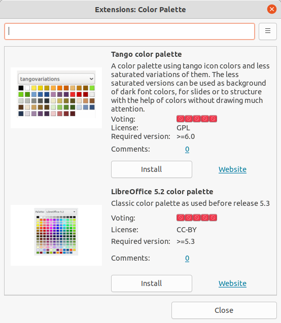
3) In Colors, click on Add color palettes via extension to open the Extensions: Color Palette dialog (Figure 19).
4) Select a color palette from the list of available color palette extensions and click on Install to install the extension into LibreOffice.
5) Click on Close to close the Extensions: Color Palette dialog and the color palette appears in the Palette drop-down list ready for use.
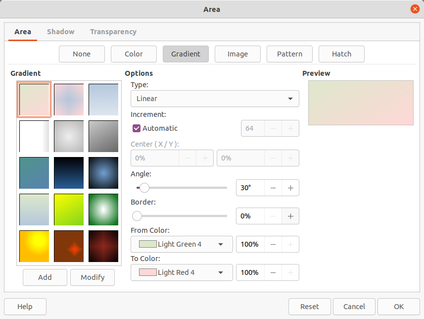
1) Select an object for editing.
2) Open the Area dialog and click on Area to open the Area page, then click on Gradient (Figure 20) to open the options available for a gradient fill.
3) In Gradient, select the required gradient from the list of available gradients and it appears in Preview.
4) To override the default gradient transition of a selection, deselect Automatic in Options and then enter the values for Type, Increment, Angle, Border, From Color, and To Color in the available boxes.
5) Click OK to close the dialog and save the changes. The area fill appears in the selected object.
Figure 20: Area dialog - Area Gradient page
Gradients can be modified or custom gradient can be created. Several types of gradients are predefined in LibreOffice and changing the From Color and To Color settings could be sufficient to obtain a satisfactory result.
1) Select the object where a custom gradient is going to be used.
2) Open the Area dialog and click on Area to open the Area page, then click on Gradient to open the options available for a gradient fill.
3) Select one of the predefined gradients shown in the Gradient box and the gradient appears in Preview.
4) In Options, select a gradient type from the Type drop-down list: Linear, Axial, Radial, Ellipsoid, or Square. Each gradient type changes the gradient displayed in Preview.
5) Adjust the settings in Options as necessary. The options used to create a gradient are summarized in Table 1. Depending on the gradient type selected, some options will not be available.
6) Click on Add and enter a name for the gradient in the Name dialog that opens.
7) Click OK to close the Name dialog and the gradient is added to the end of the gradients displayed in the Gradient box.
8) Click OK to close the Area dialog and save the changes.
Note
It is recommended to only modify, rename or delete gradients that have been created. These custom gradients are always positioned at the bottom of the gradients displayed in the Gradient box. Modifying, renaming or deleting gradients that are installed with LibreOffice may cause problems in documents that use one of these gradients.
Table 1: Gradient options
|
Gradient property |
Description |
|
Linear gradient |
The color transitions from the starting color to the end color in a straight line. |
|
Axial gradient |
The color transitions from the starting color to the end color from the object center to the object edges in two opposite directions. |
|
Radial gradient |
The color transitions from the starting color to the end color in a circular pattern. |
|
Ellipsoid gradient |
The color transitions from the starting color to the end color in an elliptical pattern. |
|
Quadratic gradient |
The color transitions from the starting color to the end color from the object edges to the object center in four directions. |
|
Square gradient |
The color transitions from the starting color to the end color from the object edges to the object center in a square pattern. |
|
Increment |
Enter the number of steps for blending the two colors of the gradient. By default this is set to Automatic. |
|
Center X |
For Radial, Ellipsoid, Square and Rectangular gradients, modify these values to set the horizontal offset of the gradient center. |
|
Center Y |
For Radial, Ellipsoid, Square and Rectangular gradients, modify these values to set the vertical offset of the gradient center. |
|
Angle |
For all gradient types, modifies the angle of the gradient axis. |
|
Border |
Increase this value to make the gradient start further away from the border of the shape. |
|
From Color |
The start color for the gradient. In the edit box enter the intensity of the color: 0% corresponds to black, 100% to the full color. |
|
To Color |
The end color for the gradient. In the edit box enter the intensity of the color: 0% corresponds to black, 100% to the full color. |
1) Select the object where the gradient is going to be modified.
2) Open the Area dialog and click on Area to open the Area page, then click on Gradient to open the options available for a gradient fill.
3) Select one of the predefined gradients shown in the Gradient box and the gradient appears in Preview.
4) Select a gradient previously created and added to the gradients displayed in the Gradient dialog.
5) Enter the new values for the gradient options that need to be changed. See Table 1 for more information on gradient options. Depending on the type of gradient selected, some options may not be available.
6) Click Modify to save the changes. There is no confirmation given when modifying a gradient.
7) Click OK to close the Area dialog and save the changes.
1) Select the object where the gradient is going to be renamed.
2) Open the Area dialog and click on Area to open the Area page, then click on Gradient to open the options available for a gradient fill.
3) Right-click on the gradient and select Rename from the context menu.
4) Enter a name for the gradient in the Name dialog that opens.
5) Click OK save the change and close the Name dialog.
6) Click OK to save the changes and close the Area dialog.
1) Select the object where the gradient is going to be deleted.
2) Open the Area dialog and click on Area to open the Area page, then click on Gradient to open the options available for a gradient fill.
3) Select a gradient that has been created and added to the gradients displayed in the Gradient box.
4) Right-click on the gradient and select Delete from the pop-up menu. Click on Yes to confirm the deletion.
5) Click OK to save the changes and close the Area dialog.
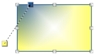
1) Select an object that contains a gradient as a fill.
2) Open the Area dialog and click on Area, then click on Gradient to open the Gradient page.
3) Go to View > Toolbars > Transformations on the Menu bar or click on Transformations on the Line and Filling toolbar to open the Transformations toolbar (Figure 21).
4) Click Interactive gradient tool in the Transformations toolbar. This displays a dashed line connecting two colored squares. The colors show the From Color and To Color that are used for the selected gradient (Figure 22).
5) Select the type of gradient required for the object from the Type drop-down list in Options on the Gradient page in the Area dialog. The gradient properties are adjusted depending on the gradient type selected and these properties are explained below.
Linear gradients – move the From Color square to change where the gradient starts (border value). Move the To Color square to change the orientation (angle value).
Axial gradients – move the To Color square to change both the angle and border properties of the gradient. Only the To Color square can be moved.
Radial gradients – move the From Color square to modify the border property to set the width of the gradient circle. Move the To Color square to change the point where the gradient ends (Center X and Center Y values).
Figure 21: Transformations toolbar
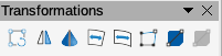
Figure 22: Example of using Interactive Gradient tool
Ellipsoid gradients – move the From Color square to modify the border property to set the size of the gradient ellipsoid. Move the To Color square to change the angle of the ellipsoid axis and the axis itself.
Quadratic gradients – move the From Color square to modify the border to set the size of the gradient square or rectangle and the angle of the gradient shape. Move the To Color square to change the center of the gradient.
Square gradients – move the From Color square to modify the border to set the size of the gradient square or rectangle and the angle of the gradient shape. Move the To Color square to change the center of the gradient.
6) Click OK to save the changes and close the Area dialog.
Note
Moving the squares creates different effects depending on the type of gradient. For example, for a linear gradient, the start and end squares of the gradient are always situated either side of the center point of the object.
Note
Image fills in the Area dialog are called bitmap fills in the drop‑down lists on the Line and Filling toolbar, and the Area panel in the Properties deck on the Sidebar.
1) Select an object for editing.
2) Open the Area dialog and click on Area to open the Area page, then click on Image (Figure 23) to open the options available for an image fill.
3) In Image, select the required image from the list of available images and it appears in Preview. Alternatively, click on Add/Import to open a file browser window, then select a file to use as an image fill.
Figure 23: Area dialog - Area Image page
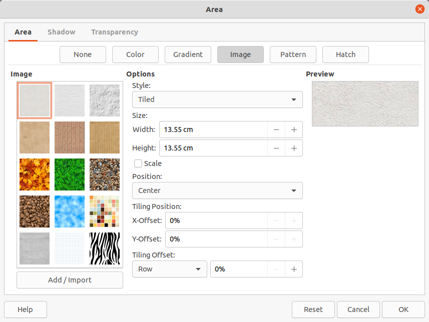
4) To override the settings for the selected image, in Options, enter values for Style, Size, Position, Tiling Position, and Tiling Offset. See Table 2 for information on Options.
5) Click OK to close the dialog and save the changes. The area fill appears in the selected object.
Table 2: Image options
|
Option |
Purpose |
|
Style – Custom position/size |
When selected, the position of the image in the object and the size of the image can be determined. |
|
Style – Tiled |
When selected, the image is tiled to fill the area. The size of the image used for the tiling is determined by the Size settings |
|
Style – Stretched |
When selected, an image is stretched to fill object area. |
|
Size – Width |
Sets the width of the image. For example, 100% means that the image original width is resized to occupy the whole fill area width, 50% means that the image width is half that of the fill area. |
|
Size – Height |
Sets the height of the image. For example, 100% means that the image original height is resized to occupy the whole fill area height, 50% means that the image height is half that of the fill area. |
|
Size – Scale |
When selected, image size is given as a percentage for Width and Height. When deselected, the actual size of the image is given for Width and Height. |
|
Position |
When selected, the anchoring point of the image is determined. Default position is Center. |
|
Tiling Position – X offset |
When Tile is selected, sets the offset for the image width in percentage values. 50% offset means that Impress places the middle part of the image at the anchor point and starts tiling from there. |
|
Tiling Position – Y offset |
When Tile is selected, sets the offset for the image height in percentage values. 50% offset means that Impress places the middle part of the image at the anchor point and starts tiling from there. |
|
Tiling Offset – Row |
When Tile is selected, offsets the rows of tiled images by the entered percentage value so that each row is offset from the previous row. |
|
Tiling Offset – Column |
When Tile is selected, offsets the columns of tiled images by the entered percentage value so that each column is offset from the previous column. |
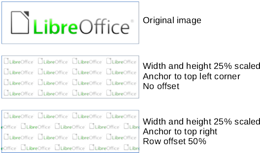
Figure 24: Example of using image fills
1) Select an object for editing that contains an image as a fill, or insert an image into a selected object
2) Open the Area dialog and click on Area to open the Area page, then click on Image to open the options available for an image fill.
3) Select an image from the options available in Image to use and edit as a fill. Note that any imported images are also available.
4) In Options, select the properties for Style, Size, Position, Tiling Position and Tiling Offset. See Table 2 for more information on bitmap properties. The best way to understand image properties is to use them. Figure 24 shows examples of using image fills.
5) Click OK to save the changes and close the Area dialog.
1) Select an object to import an image into the object.
2) Open the Area dialog and click on Area to open the Area page, then click on Image to open the options available for an image fill.
3) Click on Add/Import and a file browser window opens.
4) Navigate to the directory containing the image file, then select it and click Open.
5) Enter a name for the new image in the Name dialog that opens, then click OK to close the Name dialog. The imported image appears at the bottom of the Image preview box.
6) Select the imported image in the Image preview box.
7) Click OK to import the image into the selected object and close the Area dialog.
1) Select an object that uses an image.
2) Open the Area dialog and click on Area to open the Area page, then click on Image to open the options available for an image fill.
3) Right-click on the image selected for renaming and select Rename from the context menu.
4) Enter a new name for the image in the Name dialog that opens.
5) Click OK save the change and close the Name dialog.
6) Click OK to save the changes and close the Area dialog.
Note
It is recommended to only rename or delete images that have been created or imported. Renaming or deleting images that are installed with LibreOffice may cause problems in documents that use one of these images.
1) Select an object that contains the image being deleted.
2) Open the Area dialog and click on Area to open the Area page, then click on Image to open the options available for an image fill.
3) Right-click on the image that is going to be deleted in the Image preview box.
4) Select Delete from the context menu and click on Yes to confirm the deletion.
5) Click OK to save the changes and close the Area dialog.
1) Select an object for editing.
2) Open the Area dialog and click on Area to open the Area page, then click on Pattern (Figure 25) to open the options available for a pattern fill.
3) In Pattern, select a pattern from the available patterns and it appears in Preview.
4) Click OK to save the changes and close the Area dialog. The pattern area fill appears in the selected object.
1) Select an object that contains a pattern as a fill or insert a pattern into the selected object.
2) Open the Area dialog and click on Area to open the Area page, then click on Pattern to open the options available for a pattern fill.
Figure 25: Area dialog - Area Pattern page
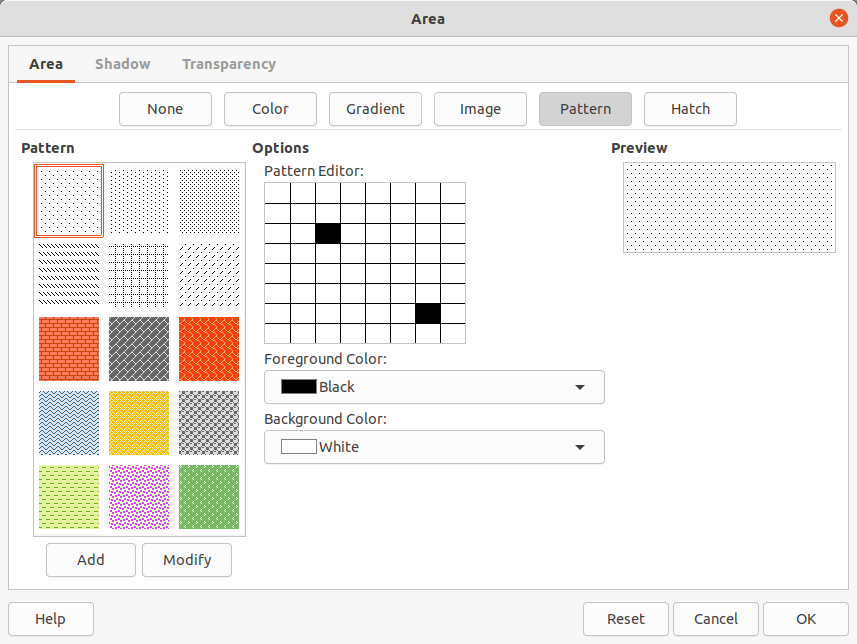
3) If necessary, select a pattern from the options available in the Pattern preview box. Note that any imported patterns are also available. The selected pattern appears in Pattern Editor.
4) In Options, select a color from the available color palettes for the Foreground Color and Background Color.
5) In Pattern Editor, start creating the pattern by clicking in the squares (pixels) to change color. Each click in a square swaps the color from Background Color to Foreground Color or Foreground Color to Background Color. Check the pattern being created to see if the desired effect is being achieved.
6) Click on Add to open a Name dialog.
7) Enter a name for the new pattern, then click OK to close the Name dialog. The new pattern appears at the bottom of the Pattern preview box.
8) Click OK to save the changes and close the Area dialog.
Note
It is recommended to only modify, rename or delete patterns that have been created. Modifying, renaming or deleting patterns that were installed with LibreOffice may cause problems in documents that use one of these patterns.
1) Select an object that contains a pattern or insert a pattern into the selected object.
2) Open the Area dialog and click on Area to open the Area page, then click on Pattern to open the options available for a pattern fill.
3) If necessary, select a pattern from the options available in the Pattern preview box. Note that any imported patterns are also available. The selected pattern appears in Pattern Editor.
4) Enter new colors for the Foreground Color and Background Color from the available color palettes.
5) In Pattern Editor, start modifying the pattern by clicking in the squares (pixels) to change color. Each click in a square swaps the color from Background Color to Foreground Color or Foreground Color to Background Color. Check the pattern being created to see if the desired effect is being achieved.
6) Click on Modify to save the pattern changes. There is no confirmation given when modifying a pattern fill.
7) Click OK to close the Area dialog and save the changes.
1) Select an object that contains a pattern, or insert a pattern into the selected object.
2) Open the Area dialog and click on Area to open the Area page, then click on Pattern to open the options available for a pattern fill. The selected pattern appears in Pattern Editor.
3) Right-click on the pattern for renaming in the Preview box and select Rename from the context menu.
4) Enter a name for the pattern in the Name dialog that opens.
5) Click OK save the renaming and close the Name box.
6) Click OK to save the changes and close the Area dialog.
1) Select an object that contains a pattern, or insert a pattern into the selected object.
2) Open the Area dialog and click on Area to open the Area page, then click on Pattern to open the options available for a pattern fill. The selected pattern appears in Pattern Editor.
3) Right-click on the pattern for deletion in the Preview box and select Delete from the context menu.
4) Click on Yes to confirm the deletion.
5) Click OK to save the changes and close the Area dialog.
1) Select an object for editing.
2) Open the Area dialog and click on Area to open the Area page, then click on Hatch to open the options available for a hatch fill (Figure 26).
3) Select a hatch from the options shown in the Hatch box and the selected hatch appears in the Preview box.
4) If necessary, to override the Options settings for the selected hatch fill, enter a new values for Spacing, Angle, Line type, Line color, and Background Color.
Figure 26: Area dialog - Area Hatch page
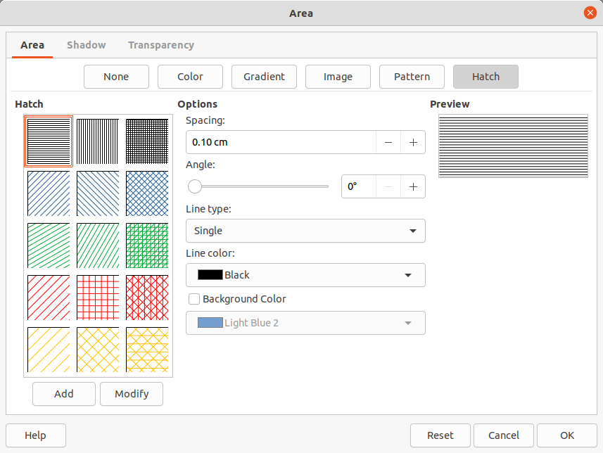
5) Click OK to save the changes and close the Area dialog. The hatch fill appears in the selected object.
When creating new hatch fills or modifying an existing hatch fill, use the options available on the Area Hatch page in the Area dialog. See Table 3 for an explanation of the options available for a hatch fill.
Note
It is recommended to create a new hatch fill rather than modify an existing hatch fill.
1) Select an object that contains a hatch fill, or insert a hatch fill into the selected object.
2) Open the Area dialog and click on Area to open the Area page, then click on Hatch to open the options available for a hatch fill.
3) As a starting point, select a hatch fill similar to the one being created. The selected hatch fill appears in the Preview box.
4) Change the values of the option settings for the hatch fill. The hatch fill displayed in the Preview box changes to reflect the changes in option values.
5) Click on Add to open the Name dialog and enter a name for the new hatch fill.
6) Click OK to close the Name dialog. The new hatch fill appears at the bottom of the hatch fills displayed in the Hatch box.
7) Click OK to close the Area dialog and save the changes. The new hatch fill appears in the selected object.
Table 3: Hatch fill options
|
Hatch option |
Meaning |
|
Spacing |
Determines the spacing between two lines of the hatching fill. As the value is changed the Preview is updated. |
|
Angle |
Determines the angle used for the hatch lines. Either use the slider or enter a value in the box to change the angle. |
|
Line type |
Set single, double or triple line for the style of the hatching fill. |
|
Line color |
Select a color of the lines that form the hatching fill from the drop‑down list of available color palettes |
|
Background color |
Select a color for the background color behind the hatching lines from the drop‑down list of available color palettes |
Note
It is recommended to only modify, rename or delete hatch fills that have been created. Modifying, renaming or deleting hatch fills that were installed with LibreOffice may cause problems in documents that use one of these hatch fills.
1) Select the object that contains the hatch fill that is to be modified.
2) Open the Area dialog and click on Area to open the Area page, then click on Hatch to open the options available for a hatch fill.
3) Enter new values for the option settings of the hatch fill. The hatch fill displayed in the Preview box changes to reflect the changes in option values. See Table 3 for information on hatch options.
4) Click Modify to save the changes. There is no confirmation given when modifying a hatch fill.
5) Click OK to save the changes and close the Area dialog.
1) Select the object that contains the hatch fill that is to be renamed.
2) Open the Area dialog and click on Area to open the Area page, then click on Hatch to open the options available for a hatch fill.
3) Right-click on the hatch fill displayed in the Hatch box and select Rename from the context menu.
4) Enter a name for the hatch fill in the Name dialog that opens.
5) Click OK to save the renaming and close the Name dialog.
6) Click OK to save the changes and close the Area dialog.
1) Select the object that contains the hatch fill that is to be deleted.
2) Open the Area dialog and click on Area to open the Area page, then click on Hatch to open the options available for a hatch fill.
3) Right-click on the hatch fill displayed in the Hatch box and select Delete from the context menu.
4) Click on Yes to confirm the deletion.
5) Click OK to save the changes and close the Area dialog.
Shadows can be applied to objects such as lines, shapes and text. The options available for shadows are as follows:
Position grid – select one of nine points determining the direction in which the shadow is cast from the object. Only available in the Shadow page of the Area dialog (Figure 27).
Angle – determines the angle in which the shadow is cast from the object. Only available in the Shadow panel in the Properties deck on the Sidebar.
Distance – determines the offset distance between the object and the shadow.
Color – sets the color used for the shadow.
Blur – sets how much the edges of a shadow are blurred or softened.
Transparency – determines the amount of transparency for the shadow: 0% opaque shadow, 100% transparent shadow.
1) Select an object where a shadow is going to be applied.
2) Open the Area dialog and click on Shadow to open the Shadow page (Figure 27).
3) Select Use shadow in Properties and the shadow options become active.
4) Select from one of nine points the direction in which the shadow is going to be cast in relation to the object.
5) In Color, select the color palette from the drop-down list of available palettes and then select the color required for the shadow.
6) In Distance, enter a distance to set spacing between the object and the shadow.
7) In Blur, enter a value to soften the edges of the shadow.
8) In Transparency, enter the percentage in the text box for the shadow transparency.
9) Click OK to close the Area dialog and save the changes.
Figure 27: Area dialog – Shadow page
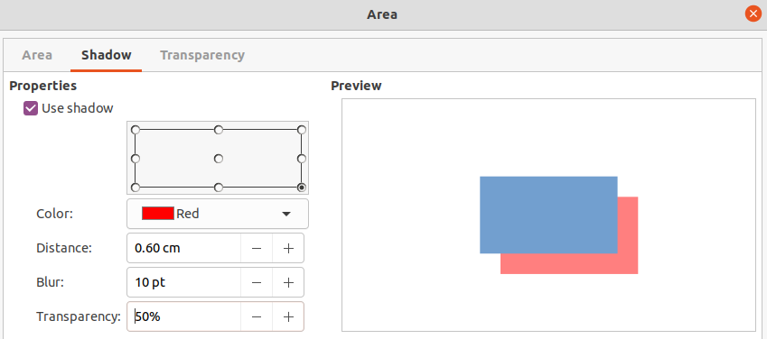
Figure 28: Shadow panel in Properties deck on Sidebar
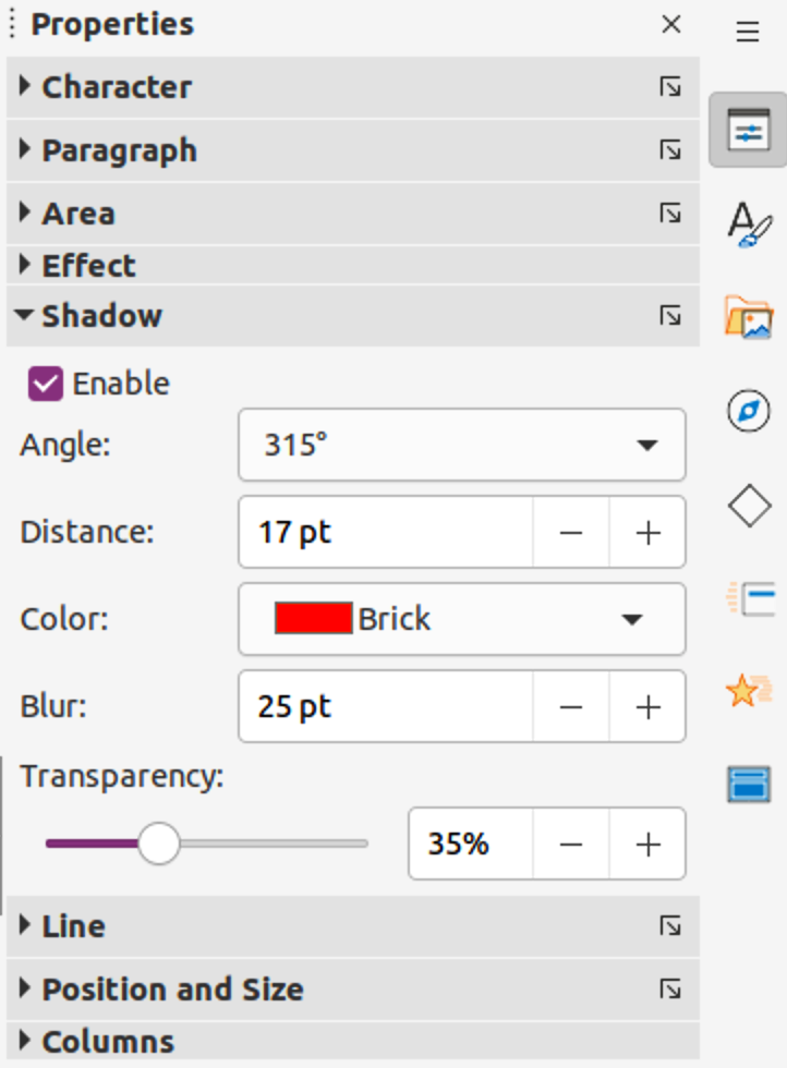
1) Select an object where a shadow is going to be applied.
2) Click on Properties to open the Properties deck on the Sidebar.
3) Click on Shadow to open the Shadow panel (Figure 28) in the Properties deck.
4) Select Enable and the shadow options become active.
5) In Angle, select from one of the options available from the drop-down list to set the direction of where the shadow is going to be cast in relation to the object.
6) In Distance, enter a distance to set spacing between the object and the shadow.
7) In Color, select the color palette from the drop-down list of available palettes and then select the color required for the shadow.
8) In Blur, enter a value to soften the edges of the shadow.
9) In Transparency, move the slider or enter a percentage in the text box to set the shadow transparency.
10) Deselect the object to save the changes made.
1) Select an object where a shadow is going to be applied.
2) Click on Shadow on the Line and Filling toolbar. A shadow is created using the settings from the Shadow page in the Area dialog.
3) Deselect the object to save the changes made.
Figure 29: Area dialog - Transparency page
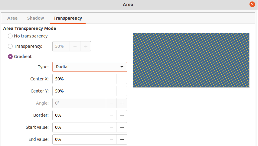
Transparencies can be applied to objects and to any shadow that has been applied to an object. In Impress two types of transparencies can be applied to an object – uniform transparency and gradient transparency. For more information on gradient transparencies, including an example of combining a color gradient with a gradient transparency, see “Gradient fills” on page 1.
1) Select an object where a transparency is going to be applied.
2) Open the Area dialog and click on Transparency to open the Transparency page (Figure 29).
3) To create a uniform transparency, select Transparency and enter a percentage in the text box.
4) To create a gradient transparency so that the area becomes gradually transparent, select Gradient and select the type of gradient transparency from the Type drop-down list: Linear, Axial, Radial, Ellipsoid, Quadratic or Square.
5) If a gradient transparency has been selected, set the parameters for the type of the gradient transparency that has been selected. Refer to Table 4 for a description of the properties. The available parameters depends on the type of gradient transparency.
6) Click OK to close the Area dialog and save the changes.
Table 4: Gradient transparency options
|
Gradient transparency options |
Meaning |
|
Center X |
Used for Radial, Ellipsoid, Quadratic and Square gradients. The values to set the horizontal offset of the gradient center. |
|
Center Y |
Used for Radial, Ellipsoid, Quadratic and Square gradients. The values to set the vertical offset of the gradient center. |
|
Angle |
Used for Linear, Axial, Ellipsoid, Quadratic and Square gradients. Specifies the angle of the gradient axis. |
|
Border |
Increase this value to make the gradient start further away from the border of the object. |
|
Start value |
Value for the starting transparency gradient. 0% is fully opaque, 100% means fully transparent. |
|
End value |
Value for the ending transparency gradient. 0% is fully opaque, 100% means fully transparent. |
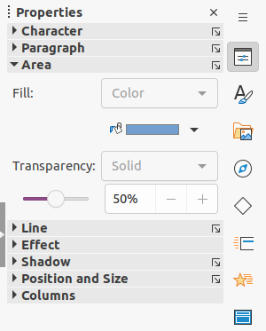
1) Select an object where a transparency is going to be applied.
2) Open the Area panel in the Properties deck on the Sidebar (Figure 30).
3) Click on the Transparency option box to open a drop-down list of available options.
4) To create a uniform transparency, select Solid and use the slider or text box to change the transparency percentage.
5) To create a gradient transparency so that the area becomes gradually transparent, select from the Transparency drop-down list either Linear, Axial, Radial, Ellipsoid, Quadratic or Square.
6) If a gradient transparency has been selected, set the parameters for the type of the gradient transparency that has been selected. Refer to Table 4 for a description of the properties. The available parameters depends on the type of gradient transparency.
7) Click away from the object to deselect it and save the changes.
Figure 30: Area panel in Properties deck on Sidebar
By default, an object is not dynamic when it is created and does not behave like a text box. If the text exceeds the object borders, then the text has to be reduced in font size, or the object size increased to accommodate the text.
1) Select the object where text is to be added.
2) Put the selected object into text mode using one of the following methods. The cursor becomes a flashing text cursor centrally inside the object indicating text mode is active. The Text Formatting toolbar automatically opens replacing the Line and Filling toolbar.
Double-click on the object.
Use the keyboard shortcut F2.
Go to Insert > Text Box on the Menu bar.
Click on Insert Text Box on the Standard or Drawing toolbar to insert horizontal text.
Click on Insert Vertical Text n the Standard or Drawing toolbar to insert vertical text.
Note
If double-clicking does not work, go to View > Toolbars on the Menu bar to open the Options toolbar, then select Double-click to edit Text.
3) Type the required text. Horizontal text is centrally aligned horizontal and vertically within the boundaries of the object. Vertical text is centrally on the left side of the object.
4) Alternatively, copy and paste text into the selected object. It is recommended to paste text into an object as unformatted text and then format the text to to the presentation requirements.
5) When finished, click outside of the object or press Esc to cancel text mode. The Line and Filling toolbar automatically opens replacing the Text Formatting toolbar.
Note
Vertical text is only available if Asian and/or Complex text layout have been selected in Tools > Options > Language Settings > Languages (macOS LibreOffice > Preferences > Language Settings > Languages).
This section only covers formatting of how text appears inside an object. For more information on formatting text attributes, see Chapter 3, Adding and Formatting Text.
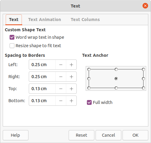
1) Select the object which contains text and use one of the following methods to open the Text dialog (Figure 31):
Go to Format > Object and Shape > Text Attributes on the Menu bar.
Right-click on the text inside the object and select Text Attributes from the context menu.
2) Click on Text to open the Text page.
3) Format and edit the text within an object using the available options. The options are described in Table 5.
4) Click OK to close the Text dialog and save the changes to the text.
Figure 31: Text dialog
5) To format the text attributes (for example paragraph alignment or font type) use the tools available on the Text Formatting toolbar, or go to Format > Text on the Menu bar and use the options available in the drop-down menu. See Chapter 3, Adding and Formatting Text for more information on formatting text attributes.
Table 5: Object text formatting options
|
Text options |
Meaning |
|
Word wrap text in shape |
Starts a new line automatically when the border of the object is reached. |
|
Resize shape to fit text |
Expands an object when the text inserted in the object is too large. |
|
Spacing to borders |
Specify the amount of space between the borders of the object and the text. |
|
Text anchor |
Used to anchor the text to a particular point within the object. |
|
Full width |
Anchors the text in the center of the object and uses the full width of the object before wrapping text. |
Text can be animated when it has been placed into an object and is a separate animation from object animation. For information on object animation, see Chapter 5, Managing Graphic Objects.
1) Select the object which contains text.
2) Open the Text dialog and click on Text Animation to open the Text Animation page (Figure 32).
3) Select the type of animation required from the Effect drop-down list as follows:
No animation – default setting.
Blink – the text blinks on the screen.
Figure 32: Text dialog - Text Animation page
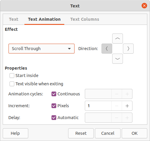
Scroll through – the text moves into the object and then out following the selected direction.
Scroll back and forth – the text moves first in the selected direction, but bounces back at the object border.
Scroll in – the text scrolls in towards the given direction starting from the edge of the object and stops in the center.
4) Set the Direction of the animation using one of the four arrows to set the scroll direction for the text.
5) Set the Properties for the animation using the following options:
Start inside – animation starts from inside the object.
Text visible when editing – select to see the text while editing.
Animation cycles – select Continuous and the text animates continuously or set a specific number of cycles for the animation.
Increment – sets the amount the animation moves in Pixels when selected or a specific distance when Pixels is deselected. The units of measurement depends on the settings in Tools > Options > LibreOffice Impress > General (macOS LibreOffice > Preferences > LibreOffice Impress > General).
Delay – starts the animation when Automatically is selected or after a specific length of time when Automatically is deselected.
6) Click OK to close the Text dialog and save the animation effect.
When text columns are added to an object, the whole of the object is used for the text columns.
1) Select the object which contains text.
2) Open the Text dialog and click on Text Columns to open the Text Columns page (Figure 33).
Figure 33: Text dialog - Text Columns page
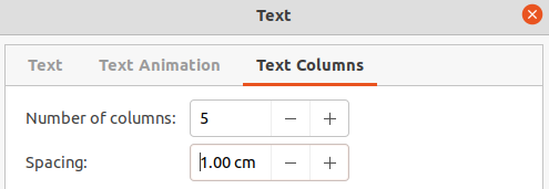
3) Enter the number of columns required in the Number of columns box.
4) Enter the spacing required between each column in the Spacing box. The units of measurement depends on the settings in Tools > Options > LibreOffice Impress > General (macOS LibreOffice > Preferences > LibreOffice Impress > General).
5) Click OK to close the Text dialog and save the changes.
Connectors are lines that join two objects and always start from or finish at a glue point on an object. See Chapter 5, Managing Graphic Objects for a description and use of the connectors.
1) Right-click on a connector and select Connector from the context menu to open the Connector dialog (Figure 34). The Connector dialog displays a preview of a connector as changes are made.
2) Select the type of connector from the Type drop-down list.
3) Set the Line skew for the connector. Line skew is used to set the distance between connectors where multiple connectors overlap.
Figure 34: Connector dialog
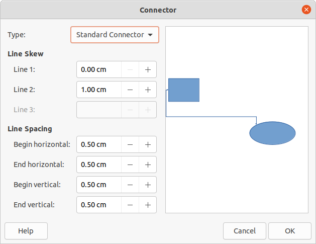
4) Set the Line spacing for the connector. Line spacing is used to set the horizontal and vertical space between the connector and the object at each end of the connector.
5) Click OK to close the Connector dialog and save the changes.
To achieve consistency in slides, a presentation, or applying the same formatting to a large number of objects, it is recommended to use styles. In Impress, styles used for objects are called drawing styles.
Drawing styles are similar to paragraph styles that are used for text. A drawing style groups all formatting properties applicable to an object and associates this properties group with a name. This allows the properties group to be used for other objects. If a drawing style is modified (for example, changing area color), the changes are automatically applied to all objects that use the same drawing style.
If Impress is used frequently, a library of well defined drawing styles is an invaluable tool for speeding up the process of formatting objects to any requirements that have to be followed (for example, company colors or fonts).
For more information on drawing styles in Impress, see Chapter 2, Slide Masters, Styles, and Templates.
Drawing styles support inheritance which allows a style to be linked to another (parent) style so that it inherits all the formatting settings of the parent. This inheritance creates families of styles.
For example, if multiple boxes are required that only differ in color, but are otherwise identically formatted, it is recommended to define a style for the box including borders, area fill, font, and so on as the parent drawing style. A number of drawing styles are then created that are hierarchically dependent to the parent style, but differing only in the fill color attribute. These drawing styles are known as child styles. If it is necessary to change the font size or border thickness, the parent style is changed and all the child styles change accordingly.
Figure 35: Drawing styles in Styles deck on Sidebar
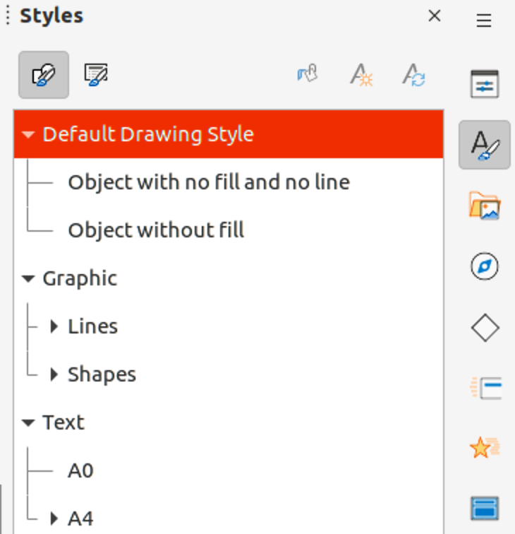
In Impress, the drawing styles are located in the Styles deck on the Sidebar (Figure 35). Click on Drawing Style to open the drawing styles that are available in the presentation. The Default Drawing Style cannot be deleted and is automatically applied to any graphic object created on a slide. This style is the starting point for creating new drawing styles.
Note
The Default Drawing Style can be modified. However, a modified Default Drawing Style only applies to the presentation where the style was modified.
1) Select an object or create a new object.
2) Open the Styles deck on the Sidebar using one of the following methods:
Click on Styles at the side of the Sidebar.
Click on Show the Styles Sidebar on the Line and Filling toolbar.
Use the keyboard shortcut F11.
3) Click on Drawing Styles on the left of the Styles title bar to open the Drawing Styles panel.
4) Right-click on a drawing style that is selected in the list and select New from the context menu to open the Graphic Styles dialog (Figure 36).
5) Click on Organizer to open the Organizer page.
6) Enter a name for the new drawing style in the Name text box.
7) In Inherit from text box, select None from the drop-down list if the new drawing style is NOT going to be linked. When the object was created, it was allocated the Default Drawing Style and this new drawing style linked by default to the Default Drawing Style.
8) Use the various pages in the Graphic Styles dialog to format the new style.
Font, Font Effects, Indents & Spacing, Alignment, Tabs, Highlighting and Asian Typography – provides options for formatting any text inserted into a graphic object.
Dimensioning – provides options for formatting of dimension lines.
Text, Text Animation, Connector, Line, Area, Shadowing, and Transparency – provides options for formatting of graphic objects.
Click OK to close the Graphics Styles dialog and save the new drawing style.
Figure 36: Graphic Styles dialog - Organizer page
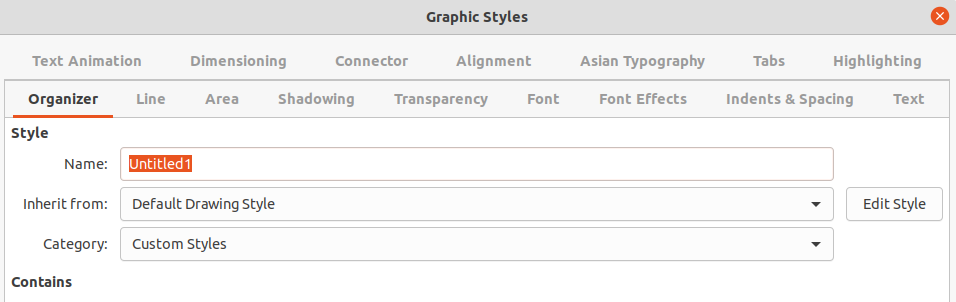
Figure 37: New Style from Selection dialog
Note
Any new drawing style created is automatically placed in the Custom Styles category.
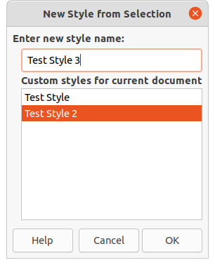
1) Select an object to use for creating a new drawing style.
2) Carry out any formatting changes to the object using the various dialogs and menu options available in Impress.
3) Open the Styles deck on the Sidebar and click on Drawing Styles on the left of the Styles title bar to open the Drawing Styles panel.
4) Click on New Style from Selection on the right of the Styles deck title bar to open the New Style from Selection dialog (Figure 37).
5) Enter a name for the new drawing style in the Enter new style name text box. A list is displayed of existing custom styles of that are available.
6) Click OK to save the new drawing style and close the New Style from Selection dialog.
1) Open the Styles deck on the Sidebar and click on Drawing Styles on the left of the Styles title bar to open the Drawing Styles panel.
2) Right-click on the style that is to be modified and select Modify from the context menu to open the Graphic Styles dialog.
3) Carry out any formatting changes to the drawing style using the options in the various pages of the Graphic Styles dialog.
4) Click OK to save the changes and close the Graphic Styles dialog.
1) Select an object or create a new object.
2) Carry out any formatting changes to the object using the various dialogs and menu options available in Impress.
3) Open the Styles deck on the Sidebar and click on Drawing Styles on the left of the Styles title bar to open the Drawing Styles panel.
4) Click on Update Style on the right of the Styles deck title bar to update the style. There is no confirmation that the style has been updated.
1) Open the Styles deck on the Sidebar and click on Drawing Styles on the left of the Styles title bar to open the Drawing Styles panel.
2) Select an object in the presentation to apply a drawing style.
3) Double-click on the drawing style name and apply the drawing style to the selected object.
The predefined drawing styles in Impress cannot be deleted, even if the predefined drawing style is not in use. Only custom (user defined) styles can be deleted.
1) Open the Styles deck on the Sidebar and click on Drawing Styles on the left of the Styles title bar to open the Drawing Styles panel.
2) Right-click on a custom drawing style and click Delete on the context menu.
3) Click Yes to confirm the deletion of the custom drawing style.
Note
Before deleting a custom drawing style, make sure the style is not in use in the presentation.